Introductory Circuit Analysis (13th Edition)
Introductory Circuit Analysis (13th Edition)
13th Edition
ISBN: 9780133923605
Author: Robert L. Boylestad
Publisher: PEARSON
expand_more
expand_more
format_list_bulleted
Bartleby Related Questions Icon
Related questions
bartleby
Concept explainers
Question
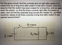
Transcribed Image Text:For the given circuit, find the currents and (a) right after switch S is
closed and (b) a long time after switch S has been closed. Let's now
assume that the switch has been closed for a long time, and we again
open the switch. (c) find the three currents right after the switch is
open, and (d) find the potential drop across the resistor R2. (e) What
would be values of all three currents a long time after switch S was
opened second time?
to
R=120n
R=30r
L%3D3H
%3D
Expert Solution
Check MarkThis question has been solved!
Explore an expertly crafted, step-by-step solution for a thorough understanding of key concepts.
bartleby
Step by stepSolved in 4 steps
Knowledge Booster
Background pattern image
Learn more about
Need a deep-dive on the concept behind this application? Look no further. Learn more about this topic, electrical-engineering and related others by exploring similar questions and additional content below.Similar questions
- (a) defibrillator sends a 6 A current through the chest of a patient by applying a 11000 V potential as in the figure. What is the resistance of the path (through the wire and the body)? -aira R= (b) The defibrillator paddles make contact with the patient through a conducting gel that greatly reduces the path resistance. To understand the importance of using the gel, discuss the difficulties that would ensue if a larger voltage were used to produce the same current through the patient, but with the path having perhaps 50 times the resistance by finding the ratio, P no-gel P gel e- ΚΩ (Hint: The current must be about the same, so a higher voltage would imply greater power. Use this equation for power: P = PR.) What difficulties arise when no gel is used? a. The voltage is too high for the human body even when the current is the same. b. There is a risk of skin burns because of the high power deposited.arrow_forwardonly 3arrow_forwardinvestigates and explains in detail the concept of induced current and induced voltagearrow_forward
- Suppose the three branch currents in this circuit are I1 = -3 A, I2 = -18 A, and I3 = -15 A. The voltage drop across each circuit element is as given in the table below. From this information, determine, for each of these circuit elements, (i) whether an active or passive sign convention is being used for that element, (ii) whether that element is absorbing or producing a net (positive) amount of electrical power. In each answer box within the table below, type the correct choice from among the bold-faced words above. V2 B A B A C D 11 A B 12 12 + Circuit element Voltage drop Sign convention? Absorbing or producing net electrical power? -9 V -2 V C 9 V -11 V Darrow_forward1.4 The charge cycle shown in Figure PL4 is an example of a three-rate charge. The current is held constant at 30 mA for 6 h. Then it is switched to 20 mA for the next 3 h. Find: a. The total charge transferred to the battery. b. The energy transferred to the battery.Page 58 Hint: Recall that energy w is the integral of power, or P = dw/dr. 1.7 V 1.2 V 9.6V 05 V 30 mA 20 mA Figure P14 3h 3h 6h 6h 9h 7arrow_forwardcan someone help me with parts A-C and explain the concepts for the slope parts explain how exactly you are getting those numbersarrow_forward
- You are an electrician working on an overhead crane. The crane uses a large electromagnet to pick up large metal pipes. The magnet must have a minimum of 200 VDC to operate properly. The crane has an AC source of 240 V. You are given four diodes that have a peak voltage rating of 400 V each. These diodes are to be used to form a bridge rectifier to convert the AC voltage into DC voltage. Is the voltage rating of the diodes sufficient? To the nearest volt, what will be the DC output voltage of the bridge rectifier?arrow_forwardFind the potential difference between point a and point b for the situation shown below. Here 1 = 12.0 V, E2 = 8.77 V and R1 = 4.13, R2 = 5.44 , and R3 = 2.28 0. Va - Vb = R2 V R3 R1 Warrow_forwardCan you please help me with this problem?arrow_forward
arrow_back_ios
SEE MORE QUESTIONS
arrow_forward_ios
Recommended textbooks for you
- Text book imageIntroductory Circuit Analysis (13th Edition)Electrical EngineeringISBN:9780133923605Author:Robert L. BoylestadPublisher:PEARSONText book imageDelmar's Standard Textbook Of ElectricityElectrical EngineeringISBN:9781337900348Author:Stephen L. HermanPublisher:Cengage LearningText book imageProgrammable Logic ControllersElectrical EngineeringISBN:9780073373843Author:Frank D. PetruzellaPublisher:McGraw-Hill Education
- Text book imageFundamentals of Electric CircuitsElectrical EngineeringISBN:9780078028229Author:Charles K Alexander, Matthew SadikuPublisher:McGraw-Hill EducationText book imageElectric Circuits. (11th Edition)Electrical EngineeringISBN:9780134746968Author:James W. Nilsson, Susan RiedelPublisher:PEARSONText book imageEngineering ElectromagneticsElectrical EngineeringISBN:9780078028151Author:Hayt, William H. (william Hart), Jr, BUCK, John A.Publisher:Mcgraw-hill Education,
Text book image
Introductory Circuit Analysis (13th Edition)
Electrical Engineering
ISBN:9780133923605
Author:Robert L. Boylestad
Publisher:PEARSON
Text book image
Delmar's Standard Textbook Of Electricity
Electrical Engineering
ISBN:9781337900348
Author:Stephen L. Herman
Publisher:Cengage Learning
Text book image
Programmable Logic Controllers
Electrical Engineering
ISBN:9780073373843
Author:Frank D. Petruzella
Publisher:McGraw-Hill Education
Text book image
Fundamentals of Electric Circuits
Electrical Engineering
ISBN:9780078028229
Author:Charles K Alexander, Matthew Sadiku
Publisher:McGraw-Hill Education
Text book image
Electric Circuits. (11th Edition)
Electrical Engineering
ISBN:9780134746968
Author:James W. Nilsson, Susan Riedel
Publisher:PEARSON
Text book image
Engineering Electromagnetics
Electrical Engineering
ISBN:9780078028151
Author:Hayt, William H. (william Hart), Jr, BUCK, John A.
Publisher:Mcgraw-hill Education,