Power System Analysis and Design (MindTap Course List)
Power System Analysis and Design (MindTap Course List)
6th Edition
ISBN: 9781305632134
Author: J. Duncan Glover, Thomas Overbye, Mulukutla S. Sarma
Publisher: Cengage Learning
expand_more
expand_more
format_list_bulleted
Bartleby Related Questions Icon
Related questions
Question
Can you explain and provide images or drawings of the simulation I will use to construct the circuit in virtual simulation.
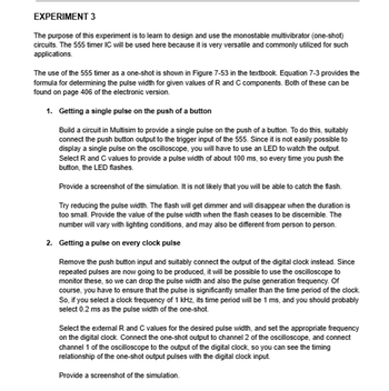
Transcribed Image Text:EXPERIMENT 3
The purpose of this experiment is to learn to design and use the monostable multivibrator (one-shot)
circuits. The 555 timer IC will be used here because it is very versatile and commonly utilized for such
applications.
The use of the 555 timer as a one-shot is shown in Figure 7-53 in the textbook. Equation 7-3 provides the
formula for determining the pulse width for given values of R and C components. Both of these can be
found on page 406 of the electronic version.
1. Getting a single pulse on the push of a button
Build a circuit in Multisim to provide a single pulse on the push of a button. To do this, suitably
connect the push button output to the trigger input of the 555. Since it is not easily possible to
display a single pulse on the oscilloscope, you will have to use an LED to watch the output.
Select R and C values to provide a pulse width of about 100 ms, so every time you push the
button, the LED flashes.
Provide a screenshot of the simulation. It is not likely that you will be able to catch the flash.
Try reducing the pulse width. The flash will get dimmer and will disappear when the duration is
too small. Provide the value of the pulse width when the flash ceases to be discernible. The
number will vary with lighting conditions, and may also be different from person to person.
2. Getting a pulse on every clock pulse
Remove the push button input and suitably connect the output of the digital clock instead. Since
repeated pulses are now going to be produced, it will be possible to use the oscilloscope to
monitor these, so we can drop the pulse width and also the pulse generation frequency. Of
course, you have to ensure that the pulse is significantly smaller than the time period of the clock.
So, if you select a clock frequency of 1 kHz, its time period will be 1 ms, and you should probably
select 0.2 ms as the pulse width of the one-shot.
Select the external R and C values for the desired pulse width, and set the appropriate frequency
on the digital clock. Connect the one-shot output to channel 2 of the oscilloscope, and connect
channel 1 of the oscilloscope to the output of the digital clock, so you can see the timing
relationship of the one-shot output pulses with the digital clock input.
Provide a screenshot of the simulation.
Expert Solution
Check MarkThis question has been solved!
Explore an expertly crafted, step-by-step solution for a thorough understanding of key concepts.
bartleby
Step by stepSolved in 2 steps with 5 images
Knowledge Booster
Background pattern image
Recommended textbooks for you
- Text book imagePower System Analysis and Design (MindTap Course ...Electrical EngineeringISBN:9781305632134Author:J. Duncan Glover, Thomas Overbye, Mulukutla S. SarmaPublisher:Cengage LearningText book imageDelmar's Standard Textbook Of ElectricityElectrical EngineeringISBN:9781337900348Author:Stephen L. HermanPublisher:Cengage LearningText book imageElectricity for Refrigeration, Heating, and Air C...Mechanical EngineeringISBN:9781337399128Author:Russell E. SmithPublisher:Cengage Learning
- Text book imageText book imageEBK ELECTRICAL WIRING RESIDENTIALElectrical EngineeringISBN:9781337516549Author:SimmonsPublisher:CENGAGE LEARNING - CONSIGNMENT
Text book image
Power System Analysis and Design (MindTap Course ...
Electrical Engineering
ISBN:9781305632134
Author:J. Duncan Glover, Thomas Overbye, Mulukutla S. Sarma
Publisher:Cengage Learning
Text book image
Delmar's Standard Textbook Of Electricity
Electrical Engineering
ISBN:9781337900348
Author:Stephen L. Herman
Publisher:Cengage Learning
Text book image
Electricity for Refrigeration, Heating, and Air C...
Mechanical Engineering
ISBN:9781337399128
Author:Russell E. Smith
Publisher:Cengage Learning
Text book image
Text book image
EBK ELECTRICAL WIRING RESIDENTIAL
Electrical Engineering
ISBN:9781337516549
Author:Simmons
Publisher:CENGAGE LEARNING - CONSIGNMENT