Introductory Circuit Analysis (13th Edition)
Introductory Circuit Analysis (13th Edition)
13th Edition
ISBN: 9780133923605
Author: Robert L. Boylestad
Publisher: PEARSON
expand_more
expand_more
format_list_bulleted
Bartleby Related Questions Icon
Related questions
Question
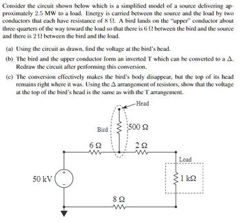
Transcribed Image Text:Consider the circuit shown below which is a simplified model of a source delivering ap-
proximately 2.5 MW to a load. Energy is carried between the source and the load by two
conductors that each have resistance of 8 2. A bird lands on the "upper" conductor about
three-quarters of the way toward the load so that there is 6 2 between the bird and the source
and there is 2 2 between the bird and the load.
(a) Using the circuit as drawn, find the voltage at the bird's head.
(b) The bird and the upper conductor form an inverted T which can be converted to a A.
Redraw the circuit after performing this conversion.
(c) The conversion effectively makes the bird's body disappear, but the top of its head
remains right where it was. Using the A arrangement of resistors, show that the voltage
at the top of the bird's head is the same as with the T arrangement.
Head
50 kV
Bird
69
www
www
892
500 2ドル
292
www
www
Load
1 kg
Expert Solution
Check MarkThis question has been solved!
Explore an expertly crafted, step-by-step solution for a thorough understanding of key concepts.
bartleby
This is a popular solution
bartleby
Trending nowThis is a popular solution!
bartleby
Step by stepSolved in 5 steps with 5 images
Knowledge Booster
Background pattern image
Learn more about
Need a deep-dive on the concept behind this application? Look no further. Learn more about this topic, electrical-engineering and related others by exploring similar questions and additional content below.Similar questions
- Q4. The source current in the circuit shown is in Figure 3a) What impedance should be connected across terminals a,b for maximum average powertransfer?b) What is the average power transferred to the impedance in (a)?c) Assume that the load is restricted to pure resistance. What size resistor connected across a,bwill result in the maximum average power transferred?d) What is the average power transferred to the resistor in (c)?varrow_forward2arrow_forwardresis to r in du cto r wired are in series of an d an i deal an battery. The in ductance of the in ductorrs 8.0 mH. and the resis tance of the battery is connected to the resirtor 2.0s2. Assume the Hle How long does it ta ke the and inductor at t>0. of its final steady ete value? Current to reach halfarrow_forward
- You have developed an idea for using a poly Si surface‐ micromachined cantilever. Initially, you designed a process flow for creating this simple structure, and the process flow is detailed in the figure below. ( cross section view and top view)There are several critical errors with this process (things that won’t work or won’t produce the result). Please find the critical errors in this process flow and, where possible, suggest alternate approaches. Do not worry about the accumulation of errors, but rather treat each step assuming that the structure up to that step could be created.This structure is actually quite simple to make. Develop a simpler process flow and associated masks to create the final structure. Be sure to show cross‐sectional and planar views of all key steps in the process.arrow_forwardConsider a circuit with a pull-down resistor in parallel to a component. Compare a resistor with higher resistance value to a resistor with lower resistance value in the parallel path. Which resistor value will pull down the potential more, relative to ground, at the high side of the component? They will pull the potential di [ Select] They will pull the potential down equally, because resistors in series have equal voltage across them, regardless of resistance value. The lower-value resistor. There is not enough information to correctly answer this question. The higher-value resistor.arrow_forward20 What is countertorque a measure of? PRACTICAL APPLICATIONS ou are working as an electrician in a large steel manufacturing plant, and Y in the of doing preventive maintenance on a large DC you are generator. You have megged both the series and shunt field windings and found that each has over 10 M2 to ground. Your ohmmeter, however, indicates a resistance of 1.5 2 across terminals S, and S,. The ohmmeter indicates a resistance of 225 N between terminals F, and F2. Are these readings normal for this type machine, or is there a likely problem? Explain your answer. processarrow_forward
- I dont understand phase shift and lags?arrow_forwardMesh current methods can greatly reduce the calculations as compared to Kirchhoff’s voltage and current laws in circuits with multiple branches. Refer to the textbook reading and the lecture for this week to answer the following post. Describe, step-by-step, the steps required to calculate all currents and voltage drops in a DC network using the Mesh Current Method.arrow_forwardfor a resistance and capicitance in a series with a voltage source, show that it is possible to draw a phasor diagram for the current and all voltages from magnitude measurment of these quantities only .illustrate your answer graphicallyarrow_forward
arrow_back_ios
arrow_forward_ios
Recommended textbooks for you
- Text book imageIntroductory Circuit Analysis (13th Edition)Electrical EngineeringISBN:9780133923605Author:Robert L. BoylestadPublisher:PEARSONText book imageDelmar's Standard Textbook Of ElectricityElectrical EngineeringISBN:9781337900348Author:Stephen L. HermanPublisher:Cengage LearningText book imageProgrammable Logic ControllersElectrical EngineeringISBN:9780073373843Author:Frank D. PetruzellaPublisher:McGraw-Hill Education
- Text book imageFundamentals of Electric CircuitsElectrical EngineeringISBN:9780078028229Author:Charles K Alexander, Matthew SadikuPublisher:McGraw-Hill EducationText book imageElectric Circuits. (11th Edition)Electrical EngineeringISBN:9780134746968Author:James W. Nilsson, Susan RiedelPublisher:PEARSONText book imageEngineering ElectromagneticsElectrical EngineeringISBN:9780078028151Author:Hayt, William H. (william Hart), Jr, BUCK, John A.Publisher:Mcgraw-hill Education,
Text book image
Introductory Circuit Analysis (13th Edition)
Electrical Engineering
ISBN:9780133923605
Author:Robert L. Boylestad
Publisher:PEARSON
Text book image
Delmar's Standard Textbook Of Electricity
Electrical Engineering
ISBN:9781337900348
Author:Stephen L. Herman
Publisher:Cengage Learning
Text book image
Programmable Logic Controllers
Electrical Engineering
ISBN:9780073373843
Author:Frank D. Petruzella
Publisher:McGraw-Hill Education
Text book image
Fundamentals of Electric Circuits
Electrical Engineering
ISBN:9780078028229
Author:Charles K Alexander, Matthew Sadiku
Publisher:McGraw-Hill Education
Text book image
Electric Circuits. (11th Edition)
Electrical Engineering
ISBN:9780134746968
Author:James W. Nilsson, Susan Riedel
Publisher:PEARSON
Text book image
Engineering Electromagnetics
Electrical Engineering
ISBN:9780078028151
Author:Hayt, William H. (william Hart), Jr, BUCK, John A.
Publisher:Mcgraw-hill Education,