Introductory Circuit Analysis (13th Edition)
Introductory Circuit Analysis (13th Edition)
13th Edition
ISBN: 9780133923605
Author: Robert L. Boylestad
Publisher: PEARSON
expand_more
expand_more
format_list_bulleted
Bartleby Related Questions Icon
Related questions
bartleby
Concept explainers
Question
thumb_up100%
Transcribed Image Text:INTRODUCTION
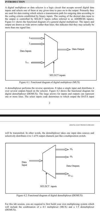
A digital multiplexer or data selector is a logic circuit that accepts several digital data
inputs and selects one of them at any given time to pass on to the output. Primarily they
are used for data routing which selects a transmission path for outgoing data according to
the coding criteria established by binary inputs. The routing of the desired data input to
the output is controlled by SELECT inputs (often referred to as ADDRESS inputs).
Figure 4.1 shows the functional diagram of a general digital multiplexer. The inputs and
output are drawn as wide arrows rather than lines; this indicates that they may actually be
more than one signal line.
Ior
I1
Data Inputs
IN-1
Data
Input
SELECT inputs
Figure 4.1: Functional diagram of digital multiplexer (MUX)
A demultiplexer performs the reverse operations. It takes a single input and distributes it
over several outputs based on the selector. Figure 4.2 shows the functional diagram for
digital demultiplexer (DEMUX). The large arrows for inputs and outputs can represent
one or more lines. The select inputs code determines to which output the DATA input
2
Data Output
will be transmitted. In other words, the demultiplexer takes one input data sources and
selectively distributes it to 1 of N output channels just like a multiposition switch.
SELECT inputs
DIGITAL ELECTRONICS STB24403
Data Outputs
ON-1
Figure 4.2: Functional diagram of digital demultiplexer (DEMUX)
For this lab session, you are required to first build your own multiplexing system which
will include the combination of a 4:1 multiplexer (MUX) and a 1:5 demultiplexer
(DEMUX).
Expert Solution
Check MarkThis question has been solved!
Explore an expertly crafted, step-by-step solution for a thorough understanding of key concepts.
bartleby
This is a popular solution
bartleby
Trending nowThis is a popular solution!
bartleby
Step by stepSolved in 4 steps with 2 images
Knowledge Booster
Background pattern image
Learn more about
Need a deep-dive on the concept behind this application? Look no further. Learn more about this topic, electrical-engineering and related others by exploring similar questions and additional content below.Similar questions
- Write verilog code for priority encoder.arrow_forwardIn a DPCM system, the number of bits per sample is 7. How many levels are present in the quantizer?arrow_forward30) Coils labeled ( S ) and ( R )A) must appear in that order (S before R) in a ladder logic programB) may be used only in subroutines in programs for Siemens PLCsC) are Short and Repeated coils, used in timing programsD) may be used instead of a seal-in arrangement to provide latchingarrow_forward
- 6. Which of the following is not a type of signal is... a. analog signalb. Chain signalc. Binary signald. Dict signale. digital signalarrow_forwardorescribed action accordingly. A) Regulating trade, B) monitoring functions. C) measure physical quantities, D) standard units. 2)A--------- a an output that varies in discrete steps and so can only have a finite number of values. A) Analogue instruments, B) digital instrument, C) Null-type ,D) passive instrument. ) a good measurement technician can substantially reduce errors at the output of a measurement system by---------?arrow_forwardnot use ai pleasearrow_forward
arrow_back_ios
arrow_forward_ios
Recommended textbooks for you
- Text book imageIntroductory Circuit Analysis (13th Edition)Electrical EngineeringISBN:9780133923605Author:Robert L. BoylestadPublisher:PEARSONText book imageDelmar's Standard Textbook Of ElectricityElectrical EngineeringISBN:9781337900348Author:Stephen L. HermanPublisher:Cengage LearningText book imageProgrammable Logic ControllersElectrical EngineeringISBN:9780073373843Author:Frank D. PetruzellaPublisher:McGraw-Hill Education
- Text book imageFundamentals of Electric CircuitsElectrical EngineeringISBN:9780078028229Author:Charles K Alexander, Matthew SadikuPublisher:McGraw-Hill EducationText book imageElectric Circuits. (11th Edition)Electrical EngineeringISBN:9780134746968Author:James W. Nilsson, Susan RiedelPublisher:PEARSONText book imageEngineering ElectromagneticsElectrical EngineeringISBN:9780078028151Author:Hayt, William H. (william Hart), Jr, BUCK, John A.Publisher:Mcgraw-hill Education,
Text book image
Introductory Circuit Analysis (13th Edition)
Electrical Engineering
ISBN:9780133923605
Author:Robert L. Boylestad
Publisher:PEARSON
Text book image
Delmar's Standard Textbook Of Electricity
Electrical Engineering
ISBN:9781337900348
Author:Stephen L. Herman
Publisher:Cengage Learning
Text book image
Programmable Logic Controllers
Electrical Engineering
ISBN:9780073373843
Author:Frank D. Petruzella
Publisher:McGraw-Hill Education
Text book image
Fundamentals of Electric Circuits
Electrical Engineering
ISBN:9780078028229
Author:Charles K Alexander, Matthew Sadiku
Publisher:McGraw-Hill Education
Text book image
Electric Circuits. (11th Edition)
Electrical Engineering
ISBN:9780134746968
Author:James W. Nilsson, Susan Riedel
Publisher:PEARSON
Text book image
Engineering Electromagnetics
Electrical Engineering
ISBN:9780078028151
Author:Hayt, William H. (william Hart), Jr, BUCK, John A.
Publisher:Mcgraw-hill Education,