Introductory Circuit Analysis (13th Edition)
Introductory Circuit Analysis (13th Edition)
13th Edition
ISBN: 9780133923605
Author: Robert L. Boylestad
Publisher: PEARSON
expand_more
expand_more
format_list_bulleted
Bartleby Related Questions Icon
Related questions
Question
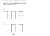
Transcribed Image Text:a)
Design a clamper circuit so that for the input waveform V,(t) as given in Figure 4(a),
the output waveform V,(t) as shown in Figure 4(b) can be produced. You shall use ideal
diode as part of your circuit design and provide the analysis of your design procedure
with the aid of the simplified equivalent circuits.
V(t)
10v-
t2
t3
t4
t5
-10V
(a)
V.(t)
15V
t1
to
t3
t4
t5
-5V
(b)
Figure 4
Expert Solution
Check MarkThis question has been solved!
Explore an expertly crafted, step-by-step solution for a thorough understanding of key concepts.
bartleby
This is a popular solution
bartleby
Trending nowThis is a popular solution!
bartleby
Step by stepSolved in 2 steps with 1 images
Knowledge Booster
Background pattern image
Learn more about
Need a deep-dive on the concept behind this application? Look no further. Learn more about this topic, electrical-engineering and related others by exploring similar questions and additional content below.Similar questions
- For the circuits shown below using ideal diodes find the values of the labeled voltages and currentsarrow_forward1. Consider the following circuit, and assume all diodes are ideal. Draw the output to for a triangular input that is given below. ~ Vin R 5 KQ www V1 5V ww D1 R1 5 ΚΩ Vin 10 f -10 D2 ww V2 5V R2 5 KQ Voarrow_forwardFor an AM DSBFC modulator with a carrier frequency f. = 100 kHz and a maximum modu- lating signal fm(max) = 5 kHz, determine a. Frequency limits for the upper and lower sidebands. b. Bandwidth. c. Upper and lower side frequencies produced when the modulating signal is a single- frequency 3-kHz tone. Then d. Sketch the output frequency spectrum.arrow_forward
- For the circuit shown below, sketch to scale the output V waveform and draw the transfer characteristic (V versus Vi), Assume the diodes are ideal.arrow_forwardPlease answer in typing format please ASAP for Like Pleasearrow_forwardFor the circuit in the figure, let V input = 8V, Ri = 12ohms, RL = 10ohms, and VZ = 3.3V. Determine the voltages and currents of the resistors and the current of the zener diode.arrow_forward
- 4.) In which mode will a diode generally not conduct electricity? a. Bidirectional Biased b. None of these c. Forward Biased d. Reversed Biased 5.) Consider the following schematic symbol of a semiconductor device: Which side is the Cathode? (Picture inserted down below) a. Side A b. Both side A and B c. Side B d. Neither side A or B 8.) Integrated circuits can be broken down into three basic categories. Which category does an operational amplifier (or op-amp) fall into? a. Analog b. None of these c. A combination of analog and digital d. Digitalarrow_forwardB. For the circuit shown below, assume that the zener diode has Vz-3.3V and rz=092 when reverse biased, and has a 0.7V drop when forward biased. Fill the following table for values of Vo for different values of input voltage Vi. R1 Vi Vi -8V OV 8V 1k 5V N V2 R21k Vo Voarrow_forwardThe circuit below has a variable voltage vin as its input. We are interested in Vout as a function of Vin. In other words, if we vary the value of the voltage source vin, what will be the effect on the voltage Vout? The steps below will help you to investigate this question, and your answers will form the basis for a new design. Assume that the diode can be sufficiently modelled as simple diode with forward voltage of 0.7 V (you do not need Shockley's equation). Vin 100Ω M Vf = 0.7 V 2 V V outarrow_forward
arrow_back_ios
arrow_forward_ios
Recommended textbooks for you
- Text book imageIntroductory Circuit Analysis (13th Edition)Electrical EngineeringISBN:9780133923605Author:Robert L. BoylestadPublisher:PEARSONText book imageDelmar's Standard Textbook Of ElectricityElectrical EngineeringISBN:9781337900348Author:Stephen L. HermanPublisher:Cengage LearningText book imageProgrammable Logic ControllersElectrical EngineeringISBN:9780073373843Author:Frank D. PetruzellaPublisher:McGraw-Hill Education
- Text book imageFundamentals of Electric CircuitsElectrical EngineeringISBN:9780078028229Author:Charles K Alexander, Matthew SadikuPublisher:McGraw-Hill EducationText book imageElectric Circuits. (11th Edition)Electrical EngineeringISBN:9780134746968Author:James W. Nilsson, Susan RiedelPublisher:PEARSONText book imageEngineering ElectromagneticsElectrical EngineeringISBN:9780078028151Author:Hayt, William H. (william Hart), Jr, BUCK, John A.Publisher:Mcgraw-hill Education,
Text book image
Introductory Circuit Analysis (13th Edition)
Electrical Engineering
ISBN:9780133923605
Author:Robert L. Boylestad
Publisher:PEARSON
Text book image
Delmar's Standard Textbook Of Electricity
Electrical Engineering
ISBN:9781337900348
Author:Stephen L. Herman
Publisher:Cengage Learning
Text book image
Programmable Logic Controllers
Electrical Engineering
ISBN:9780073373843
Author:Frank D. Petruzella
Publisher:McGraw-Hill Education
Text book image
Fundamentals of Electric Circuits
Electrical Engineering
ISBN:9780078028229
Author:Charles K Alexander, Matthew Sadiku
Publisher:McGraw-Hill Education
Text book image
Electric Circuits. (11th Edition)
Electrical Engineering
ISBN:9780134746968
Author:James W. Nilsson, Susan Riedel
Publisher:PEARSON
Text book image
Engineering Electromagnetics
Electrical Engineering
ISBN:9780078028151
Author:Hayt, William H. (william Hart), Jr, BUCK, John A.
Publisher:Mcgraw-hill Education,