Introductory Circuit Analysis (13th Edition)
Introductory Circuit Analysis (13th Edition)
13th Edition
ISBN: 9780133923605
Author: Robert L. Boylestad
Publisher: PEARSON
expand_more
expand_more
format_list_bulleted
Bartleby Related Questions Icon
Related questions
Question
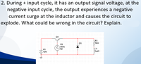
Transcribed Image Text:2. During + input cycle, it has an output signal voltage, at the
negative input cycle, the output experiences a negative
current surge at the inductor and causes the circuit to
explode. What could be wrong in the circuit? Explain.
Q1
R1
1kQ
D1
V2
1kHz
5V
L1
V1
1mH
12V
Expert Solution
Check MarkThis question has been solved!
Explore an expertly crafted, step-by-step solution for a thorough understanding of key concepts.
bartleby
Step by stepSolved in 2 steps
Knowledge Booster
Background pattern image
Similar questions
- Given the following with Q = 0 as initial state, What do the Q and Q0 waveforms look like? SET RESET Qarrow_forwardA step down converter is operated with a duty cycle of k = 0.75. The input voltage is Vs = 20V, and the load is: L = 5mH, R = 1502. The minimum inductor current is I1 = 0.1A. The maximum inductor current is: Select one: a. 1.9 A b. None of these OC. 0.9 A O d. 1.1 A Oe. 2 Aarrow_forwardPlease solve the marked question.arrow_forward
- C'uk Converter Design A C'uk converter has an input of 12 V and is to have an output of - 24 V supplying a 60 W load. Select the duty ratio, the switching frequency, the inductor sizes such that the change in inductor currents is no more than 12 percent of the average inductor current, the output ripple voltage is no more than 1.5 percent, and the ripple voltage across C1 is no more than 3 percent.arrow_forwardQ/ Draw the input and the output waveform of the circuit below and analyze the signal flowing in both half-cycles Using two different colors, and label the voltage on the waveform, then determine Vay and Vrms (Vin=5V, frequency= 1kHz) 17 wwarrow_forward
arrow_back_ios
arrow_forward_ios
Recommended textbooks for you
- Text book imageIntroductory Circuit Analysis (13th Edition)Electrical EngineeringISBN:9780133923605Author:Robert L. BoylestadPublisher:PEARSONText book imageDelmar's Standard Textbook Of ElectricityElectrical EngineeringISBN:9781337900348Author:Stephen L. HermanPublisher:Cengage LearningText book imageProgrammable Logic ControllersElectrical EngineeringISBN:9780073373843Author:Frank D. PetruzellaPublisher:McGraw-Hill Education
- Text book imageFundamentals of Electric CircuitsElectrical EngineeringISBN:9780078028229Author:Charles K Alexander, Matthew SadikuPublisher:McGraw-Hill EducationText book imageElectric Circuits. (11th Edition)Electrical EngineeringISBN:9780134746968Author:James W. Nilsson, Susan RiedelPublisher:PEARSONText book imageEngineering ElectromagneticsElectrical EngineeringISBN:9780078028151Author:Hayt, William H. (william Hart), Jr, BUCK, John A.Publisher:Mcgraw-hill Education,
Text book image
Introductory Circuit Analysis (13th Edition)
Electrical Engineering
ISBN:9780133923605
Author:Robert L. Boylestad
Publisher:PEARSON
Text book image
Delmar's Standard Textbook Of Electricity
Electrical Engineering
ISBN:9781337900348
Author:Stephen L. Herman
Publisher:Cengage Learning
Text book image
Programmable Logic Controllers
Electrical Engineering
ISBN:9780073373843
Author:Frank D. Petruzella
Publisher:McGraw-Hill Education
Text book image
Fundamentals of Electric Circuits
Electrical Engineering
ISBN:9780078028229
Author:Charles K Alexander, Matthew Sadiku
Publisher:McGraw-Hill Education
Text book image
Electric Circuits. (11th Edition)
Electrical Engineering
ISBN:9780134746968
Author:James W. Nilsson, Susan Riedel
Publisher:PEARSON
Text book image
Engineering Electromagnetics
Electrical Engineering
ISBN:9780078028151
Author:Hayt, William H. (william Hart), Jr, BUCK, John A.
Publisher:Mcgraw-hill Education,