Introductory Circuit Analysis (13th Edition)
Introductory Circuit Analysis (13th Edition)
13th Edition
ISBN: 9780133923605
Author: Robert L. Boylestad
Publisher: PEARSON
expand_more
expand_more
format_list_bulleted
Bartleby Related Questions Icon
Related questions
bartleby
Concept explainers
Question
Please do question 14
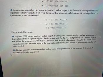
Transcribed Image Text:w 010111100110011111
z: 000000100100010011
14. A sequential circuit has two inputs, wl and w2, and an output, z. Its function is to compare the input
sequences on the two inputs. If w1 = w2 during any four consecutive clock cycles, the circuit produces z =
1; otherwise, z = 0. For example
a
w1
w2
z:
0110111000110
1110101000111
0000100001110
Derive a suitable circuit.
of
15. A given FSM has an input, w, and an output, z. During four consecutive clock pulses, a sequence
four values of the w signal is applied. Derive a state table for the FSM that produces z = 1 when it detects
that either the sequence w: 0010 or w: 1110 has been applied; otherwise, z = 0. After the fourth clock
pulse, the machine has to be again in the reset state, ready for the next sequence. Minimize the number of
states needed.
16. Design a counter that counts pulses on line w and displays the count in the sequence 0, 2, 1, 3, 0, 2,....
Use D flip-flops in your circuit.
Expert Solution
Check MarkThis question has been solved!
Explore an expertly crafted, step-by-step solution for a thorough understanding of key concepts.
bartleby
This is a popular solution
bartleby
Trending nowThis is a popular solution!
bartleby
Step by stepSolved in 5 steps with 6 images
Knowledge Booster
Background pattern image
Learn more about
Need a deep-dive on the concept behind this application? Look no further. Learn more about this topic, electrical-engineering and related others by exploring similar questions and additional content below.Similar questions
- Suppose the current in this circuit is I = -35 A. The voltage drop across each circuit element is as given in the table below. From this information, determine, for each of these circuit elements, (i) whether an active or passive sign convention is being used for that element, (ii) whether that element is absorbing or producing a net (positive) amount of electrical power. In each answer box within the table below, type the correct choice from among the bold-faced words above. - A A B C A + с B + V2 Circuit element Voltage drop Sign convention? Absorbing or producing net electrical power? -5 V -6 V 1 V -arrow_forwardA 636 kcmil 26/2 ACSR conductor has a GMR of _____ inch at 60 Hz. (Round-off answer in 3 decimal places)arrow_forwardIn an electrical system, each of the service entrance conductors has an area of 750 kcmil. The size of analuminum grounding conductor that will be brought to the service should beA. 250 kcmil.B. 4/0.C. 2/0.D. 500 kcmilarrow_forward
- If an electrical system operates at a potential higher than 600 volts, the nonmetallic conduit must be encased in at least_of concrete. A. 1 inch B. 2 inches C. 4 inches D. 6 inchesarrow_forwardPlease use the per-Square-Foot Method to answer the following question: If we figure at one 15-ampere branch circuit for every 600 ft2, a 3000 ft2 house would have a minimum of how many 15-ampere general purpose lighting branch circuits? Group of answer choices A. Four 15-ampere general purpose lighting branch circuits. B. Five 15-ampere general purpose lighting branch circuits. C. Six 15-ampere general purpose lighting branch circuits. D. Seven 15-ampere general purpose lighting branch circuits.arrow_forwardWhat is the unit E?arrow_forward
- gn In/Sign Up OSign In/Sign Up 006157 Exam +>C合 assignments.pennfoster.com/Exams/Random?qNo3DqD5EpTNrP8E%3D boTax Exam Lesson Name: Advanced Grounding Applications Exam number: 006157RR Exam Guidelines> Exam Instructions Question 14 of 20 : Select the best answer for the question. 14. Which of the following statements about the neutral ground-strap ground fault protection system is correct? O A. It can be installed only at the main service equipment. O B. It monitors only the phase conductors. O C. It monitors the grounding electrode conductor at the utility connection. O D. It monitors the equipment grounding conductor and a single phase conductor. O Mark for review (Will be highlighted on the review page)> 111arrow_forwardWhat is the minimum height of electrical service entrancearrow_forward6. Since the voltages across each branch circuit in a residence are the same, these circuits areA. connected in series.B. connected in parallel.C. controlled circuit configurations.D. complex circuit configurations. I'm not sure if it's the letter B or C, could you help me with the correct answer.arrow_forward
arrow_back_ios
SEE MORE QUESTIONS
arrow_forward_ios
Recommended textbooks for you
- Text book imageIntroductory Circuit Analysis (13th Edition)Electrical EngineeringISBN:9780133923605Author:Robert L. BoylestadPublisher:PEARSONText book imageDelmar's Standard Textbook Of ElectricityElectrical EngineeringISBN:9781337900348Author:Stephen L. HermanPublisher:Cengage LearningText book imageProgrammable Logic ControllersElectrical EngineeringISBN:9780073373843Author:Frank D. PetruzellaPublisher:McGraw-Hill Education
- Text book imageFundamentals of Electric CircuitsElectrical EngineeringISBN:9780078028229Author:Charles K Alexander, Matthew SadikuPublisher:McGraw-Hill EducationText book imageElectric Circuits. (11th Edition)Electrical EngineeringISBN:9780134746968Author:James W. Nilsson, Susan RiedelPublisher:PEARSONText book imageEngineering ElectromagneticsElectrical EngineeringISBN:9780078028151Author:Hayt, William H. (william Hart), Jr, BUCK, John A.Publisher:Mcgraw-hill Education,
Text book image
Introductory Circuit Analysis (13th Edition)
Electrical Engineering
ISBN:9780133923605
Author:Robert L. Boylestad
Publisher:PEARSON
Text book image
Delmar's Standard Textbook Of Electricity
Electrical Engineering
ISBN:9781337900348
Author:Stephen L. Herman
Publisher:Cengage Learning
Text book image
Programmable Logic Controllers
Electrical Engineering
ISBN:9780073373843
Author:Frank D. Petruzella
Publisher:McGraw-Hill Education
Text book image
Fundamentals of Electric Circuits
Electrical Engineering
ISBN:9780078028229
Author:Charles K Alexander, Matthew Sadiku
Publisher:McGraw-Hill Education
Text book image
Electric Circuits. (11th Edition)
Electrical Engineering
ISBN:9780134746968
Author:James W. Nilsson, Susan Riedel
Publisher:PEARSON
Text book image
Engineering Electromagnetics
Electrical Engineering
ISBN:9780078028151
Author:Hayt, William H. (william Hart), Jr, BUCK, John A.
Publisher:Mcgraw-hill Education,