Introductory Circuit Analysis (13th Edition)
Introductory Circuit Analysis (13th Edition)
13th Edition
ISBN: 9780133923605
Author: Robert L. Boylestad
Publisher: PEARSON
expand_more
expand_more
format_list_bulleted
Bartleby Related Questions Icon
Related questions
Question
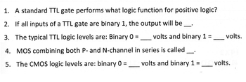
Transcribed Image Text:1. A standard TTL gate performs what logic function for positive logic?
2. If all inputs of a TTL gate are binary 1, the output will be
3. The typical TTL logic levels are: Binary 0=
4. MOS combining both P- and N-channel in series is called
5. The CMOS logic levels are: binary 0 =
volts and binary 1 =
volts.
volts and binary 1 = ______ volts.
Expert Solution
Check MarkThis question has been solved!
Explore an expertly crafted, step-by-step solution for a thorough understanding of key concepts.
bartleby
Step by stepSolved in 2 steps with 1 images
Knowledge Booster
Background pattern image
Learn more about
Need a deep-dive on the concept behind this application? Look no further. Learn more about this topic, electrical-engineering and related others by exploring similar questions and additional content below.Similar questions
- 5 Note: Please do not handwritten.arrow_forwardDefine a 2-bit demultiplexer to be a circuit whose single input line is steered to one of the four output linesdepending on the state of the two control lines (A, B). Draw its logic diagram (to the gate level) and specify the exactstate of A and B for each output line when that output line is selected.arrow_forwarda) A standard TTL inverter gate is shown in the figure. The supply voltage is 5V. Calculate the output voltage for both logic low and logic high input cases assuming input voltages respectively as 0.11V and 4.2V. Br= 130; BR = 0.24. You can make approximations when needed. Br = IcIs active region; BR = IE/ls inverse active region b) Assume you connect a resistor of 1.8K to the output of the circuit when the output is at logic high. What will be the change in the output voltage? 1302 R3 1.6k2 R, 4k2 Input o T, Output T, V, V. IkQ R,arrow_forward
arrow_back_ios
arrow_forward_ios
Recommended textbooks for you
- Text book imageIntroductory Circuit Analysis (13th Edition)Electrical EngineeringISBN:9780133923605Author:Robert L. BoylestadPublisher:PEARSONText book imageDelmar's Standard Textbook Of ElectricityElectrical EngineeringISBN:9781337900348Author:Stephen L. HermanPublisher:Cengage LearningText book imageProgrammable Logic ControllersElectrical EngineeringISBN:9780073373843Author:Frank D. PetruzellaPublisher:McGraw-Hill Education
- Text book imageFundamentals of Electric CircuitsElectrical EngineeringISBN:9780078028229Author:Charles K Alexander, Matthew SadikuPublisher:McGraw-Hill EducationText book imageElectric Circuits. (11th Edition)Electrical EngineeringISBN:9780134746968Author:James W. Nilsson, Susan RiedelPublisher:PEARSONText book imageEngineering ElectromagneticsElectrical EngineeringISBN:9780078028151Author:Hayt, William H. (william Hart), Jr, BUCK, John A.Publisher:Mcgraw-hill Education,
Text book image
Introductory Circuit Analysis (13th Edition)
Electrical Engineering
ISBN:9780133923605
Author:Robert L. Boylestad
Publisher:PEARSON
Text book image
Delmar's Standard Textbook Of Electricity
Electrical Engineering
ISBN:9781337900348
Author:Stephen L. Herman
Publisher:Cengage Learning
Text book image
Programmable Logic Controllers
Electrical Engineering
ISBN:9780073373843
Author:Frank D. Petruzella
Publisher:McGraw-Hill Education
Text book image
Fundamentals of Electric Circuits
Electrical Engineering
ISBN:9780078028229
Author:Charles K Alexander, Matthew Sadiku
Publisher:McGraw-Hill Education
Text book image
Electric Circuits. (11th Edition)
Electrical Engineering
ISBN:9780134746968
Author:James W. Nilsson, Susan Riedel
Publisher:PEARSON
Text book image
Engineering Electromagnetics
Electrical Engineering
ISBN:9780078028151
Author:Hayt, William H. (william Hart), Jr, BUCK, John A.
Publisher:Mcgraw-hill Education,