Zobrazují se příspěvky se štítkemComputer Science. Zobrazit všechny příspěvky

sobota 31. května 2014

Detecting extreme values in SQL

In a set of data points, outliers are such values that theoretically should not appear in the dataset. Typically these can be measurement errors or values caused by human mistakes. In some cases outliers are not caused by errors. These values affect the way that the data is treated and any statistics or report based on data containing outliers are erroneaus.

Detecting these values might be very hard or even impossible and a whole field of statistics called Robust Statistics covers this subject. If you are further interested into the subject please read Quantitative Data Cleaning For Large Databases written by Joseph M. Hellerstein from UC Barkeley. Everything that I have implemented here is taken from this paper. The only thing that I have added to that are two aggregates for SQL Server which help efficiently get the outliers and extreme values from the data stored in SQL Server and a simple tool to chart data and distribution of data using JavaScript

Theory

Any dataset can be characterized by the way the data is distributed over the whole range. The probability that a single point has given value in the dataset is defined using the probability distribution function. The Gaussian standard distribution is only one among many distribution functions, I won't go into statistics basics here, but let's consider only the standard distribution for our case.

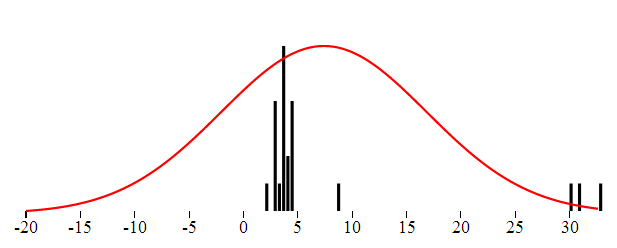
In the Gaussian distribution the data points are somehow gathered around the "center", and most values fall not far. Rare are the values really far away from the center. Intuitively the ouliers are points very far from the center. Consider the following set of numbers which represent in minutes the length of a popular song:

3.9,3.8,3.9,2.7,2.8,1.9,2.7,3.5, 4.4, 2.8, 3.4, 8.6, 4.5, 3.5, 3.6, 3.8, 4.3, 4.5, 3.5,30,33,31

You have probably spotted the values 30,33 and 31 and you immediately identify them as outliers. Even if the Doors would double the length of their keyboard solo we would not get this far.

The standard distribution can be described using the probability density function. This function defines the probability that the point will have given value. The function is defined with two parameters: the center and the dispersion. The center is the most common value, the one around which all others are gathered. The dispersion describes how far the values are scattered from the center.

The probability that a point has a given value, provided that the data has the Gaussian distribution is given by this equation:

We can visualize both the theoretical and the real distribution of data. The distribution probability density function is continuous and thus can be charted as simple line. The distribution of the real data in turn can be visualized like a histogram.

The following graphics were created using KoExtensions project, which is a small mediator project making Knockout and D3 work nicely together.

In perfect world the center is the mean value. That value is probably not a part of a data set but represents the typical value. The seconds measure which describes how far from the center the data is dispersed is called standard deviation. If we want to obtain the standard deviation from data we take the distance of each point from the center, square these values add them together and take square root. So we actually have all we need to get the distribution parameters from the data.

This approach of course has one main flaw. The mean value is affected by the outliers. And since the dispersion is deduced using the mean and outliers affect the mean value, the dispersion as well will be affected by them. In order to get a description of the dataset not affected by the extreme values one needs to find robust replacements for the mean and the dispersion.

Robust Center

The simplest and very efficient replacement for the mean as the center of the data is the median. Median is such value that half of the points in the dataset are smaller are bellow. That is if the data set consists of even number of samples, we just need to order the values and take mean of the two values in the middle of the ordered array. If the data consist of odd number of values then we take the element exactly in the middle of the ordered data. The before mentioned paper describes two more alternatives: trimmed mean, winsorized mean. Both of these are based on the exclusion of marginal values and I did not used them in my implementation.

Let's take the median of the given dataset and see if the distribution function based on it fits better the data. Even though the center is now in correct place the shape of the function does not fit completely the data from the histogram. That is because the variance is still affected by the outliers.

Robust Dispertion

Standard variance takes into account the the distance of all the numbers from the center. To rule out the extreme values, we can just use the median of distances. The outlier's distance from the center is much bigger than other distance and by taking the median of all distances we can get rid of outlier's influence over the dispersion. Here is the distribution function using this Robust type of dispersion. This characteristic is called MAD - Median Absolute Deviation.

Detecting the outliers

Now that we have the value of "real" center and "real spread" or dispersion we can state that the outlier is a value which differs "too much" from the center, taking into account the dispersion. Typically we could say that the outliers are such values that have a distance from center greater or equal to 10 * dispersion. The question is how to specify the multiplication coefficient. There is a statistics method called Hampel Indetifier which gives a formula to obtain the coefficient. Hampel identifier labels as outliers any points that are more than 5.2 away from the MAD. More details can be found here.

The overall reliability of this method

A question which might arise is up to which kind of messy data this method can be used. A common intuition would say that definitely more than the half of the data has to be "correct", in order to be able to detect the incorrect ones. To be able to measure the robustness of each method of detecting outliers, statisticians have introduced a term called Breakdown point. This point states which percentage of the data can be corrupted in order for given method to work. Using the Median as the center with the MAD (Median Absolute Deviation) has a breakdown point of 1/2. That is this method works if more than half of the data is correct. The standard arithmetic mean has a BP = 0. It is directly affected by all the numbers and one single outlier can completely move the data.

SQL implementation

In order to implement detection of outliers in SQL, one needs to first have the necessary functions to compute the mean, median and dispersion. All these functions are aggregates. Mean (avg) and Dispersion (var) are already implemented in SQL Server. If you are lucky enough to use SQL Server 2012 you can use the built-in median aggregate as well. The robust dispersion however has to be implemented manually even on SQL Server 2012.

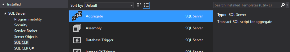
Implementing aggregates for SQL Server is very easy, thanks to the predefined Visual Studio template. This templates will create a class for you which implements the IBinarySerializable interface and is decorate with couple attributes defined in the Microsoft.SqlServer namespace.

This class has 4 important methods:

  • Init - anything needed before starting the aggregation
  • Accumulate - adding one single value to the aggregate
  • Merge - merging two aggregates
  • Terminate - work to be done before returning the result of the aggregate

Here is the example of the Median aggregate

private List ld;
public void Init()
{
 ld = new List();
}
public void Accumulate(SqlDouble value)
{
 if (!value.IsNull)
 {
 ld.Add(value.Value);
 }
}
public void Merge(Median group)
{
 ld.AddRange(group.ld.ToArray());
}
public SqlDouble Terminate()
{
 return Tools.Median(ld);
}

Note that some aggregates can be computed iteratively. In that case all the necessary logic is in the Accumulate method and the Terminate method can be empty. With Median this is not the case (even though some iterative estimation methods exist. For the sake of the completeness, here is the implementation of median that I am using. It is the standard way: sorting the array and taking the middle element or average of the two middle elements. I am returning directly SqlDouble value, which is the result of the aggregate.

public static SqlDouble Median(List ld)
{
 if (ld.Count == 0)
 return SqlDouble.Null;
 ld.Sort();
 int index = ld.Count / 2;
 if (ld.Count % 2 == 0)
 {
 return (ld[index] + ld[index - 1]) / 2;
 }
 return ld[index];
}

Implementing the Robust variance using the MAD method is very similar, everything happens inside the Terminate method.

public SqlDouble Terminate()
{
 var distances = new List();
 var median = Tools.Median(ld);
 foreach (var item in ld)
 {
 var distance = Math.Abs(item - median.Value);
 distances.Add(distance);
 }
 var distMedian = Tools.Median(distances);
 return distMedian;
}

That implementation is directly the one described above: we take the distance of each element from the center (median) and than we take the median of the distances.

Outliers detection with the SQL aggregates

Having implemented both aggregates, detecting the outlier is just a matter of a SQL query - giving all the elements which are further away from the center than the variance multiplied by a coefficient.

select * from tbUsers where Height> ( Median(Height) + c*RobustVar(Height)) or Height < (Median(Height) - c*RobustVar(Height)) 

You will have to play with the coefficient value c to determine which multiplication gives you the best results.

JavaScript implementation

The same can be implemented in JavaScript. If you are interested in a JavaScript implementation you can check out the histogram chart from KoExtensions. This charting tool draws the histogram and the data distribution function. You can than configure it to use either Median or Mean as the center of the data as well as to use MAD, or standard variance to describe the dispersion.

KoExtensions is based on Knockout.JS and adds several useful bindings and the majority of them to simplify charting. Behind the scenes the data is charted using D3.

To draw a histogram chart with the distribution and detecting the outliers at the same time one needs just few lines of code

<div id="histogram" data-bind="histogram: data, chartOptions : {
 tolerance : 10,
 showProbabilityDistribution: true,min : -20,
 expected: 'median',
 useMAD: true,
 showOutliers: true}">
var exData = [3.9,3.8,3.9,2.7,2.8,1.9,2.7,3.5, 4.4, 2.8, 3.4, 8.6, 4.5, 3.5, 3.6, 3.8, 4.3, 4.5, 3.5,30,33,31];
 
function TestViewModel() {
 var self = this;
 self.data = ko.observableArray(exData);
}
var vm = new TestViewModel();
ko.applyBindings(vm);
initializeCharts();

Knockout.JS is a JavaScript MVVM framework tool which gives you all you need to create bi-directional binding between the view and the view model, where you can encapsulate and unit test all your logic. KoExtensions adds a binding call "histogram", which takes simple array and draws a histogram. In order to show the probability function and the outliers one has to set the options of the chart as shown in the example above.

AltStyle によって変換されたページ (->オリジナル) /

čtvrtek 26. září 2013

Introduction to GPU programing through AMP C++

Few months ago I tried to learn a bit about GPU programming and I took notes a started to write this post. I am publishing this now even though it's not complete, however being too busy, I am not sure whether I will have the time to get back to this later.

Since couple years CUDA (*2007) and OpenCL (*2008) have established themselves as standard frameworks for parallel programming on the GPU. In 2011 new framework came to the landscape of GPGPU programming, which does not compete on the same level, but rather represents new abstraction between the GPU and the developer.

AMP stands for Accelerated Massive Parallelism and it is an open C++ standard. The implementation of AMP provided by Microsoft consists of three main features:

  • C++ language features and compiler
  • Runtime
  • Programming framework containing classes and functions to facilitate parallel programming

As well as OpenCL and unlike CUDA, AMP is a standard not only for GPU programming but for any data-parallel hardware. Typical example of such a hardware is the vector unit of standard CPU, capable of executing SIMD (Single Instruction Multiple Data) instructions. Or in the near future a cloud based cluster. AMP is an abstraction layer which can be used to target different devices from different vendors.

The following diagram depicts how AMP C++ fits to the world of GPGPU programming.

Microsoft has implemented AMP on top of DirectCompute technology and it is the only production ready implementation. Currently there are also two Proof Of Concepts AMP implementations Shelvin park project done by Intel and open source modification of the LLVM compiler (more information here). Needless to say that the adoption of such standard will depend a lot on whether these implementations will be taken further and whether we will have real implementation based on CUDA.

First look at the code

Without further introduction let's take a look at the classical "Hello World" of GPGPU programming: Addition of elements of two vectors (here without the boiler plate code).

parallel_for_each(e,[=](index<2>idx) restrict(amp){
 c[idx] = a[idx] + b[idx];
});

If you have ever tried out OpenCL or CUDA, you should find this piece of code less verbose and quite easy to read. That is the result of the main ideas behind AMP C++:

  • Full C++ - unlike CUDA or OpenCL, AMP is not a C like dialect.
  • Minimalist API - AMP hides as much as it can from the developer.
  • Future proofed - the API is designed for heterogeneous programming. In the future GPU should be only one of it's usages. It aims to be a standard for programming on distributed systems.

Before going futher with more examples we have to provide basic description of GPU architecture as it is crutial to understanding certain parts of AMP

GPU architecture

Here I will give a high level overview of the GPU architecture. If you are already familiar with the GPU architecture, feel free to skip this section.

Currently there are two main producers of GPU chips: NVidia and ATI (AMD). A little behind comes Intel. Each of them constructs graphic cards with different architecture. Moreover the architectures change significantly with the realease of any new version. Nevertheless certain concepts are shared by all of them. I will describe here shortly the NVidias Fermi and ATIs Cypress architecture. The succesor of Fermi is called Kepler.

Processor architecture

The GPU is composed of hundreds of pipelined cores. The cores are grouped to computation units. NVidia calls these units Symmetric Multiprocessors. Each computation unit is assigned a unit of work.

ATI uses slightly different abstraction. Similary to NVidia the "cores" are grouped to Symmetric Multiprocessors, however each core is called Thread Processor and is a capable of executing VLIV (Very Long Instruction Word) instructions. It has therefore 4 arithmetic logical units and one Special Function Unit. The compiler has to find independent operations and construct the VLIW instruction. If the compiler is not able to find these independent operations than one or more of the ALUs will not be performing any operation.

Memory access

The GPU has a global memory which can be accessed by all cores. This access is quite costly (hundreds of cycles). Each simetric multiprocessor in turn has a small scratch-pad memory which is called usually local memory. This memory can be accessed only by the threads running on the given SM. The access to local memory is much cheaper (around 10 cycles). This memory can either take a role of a cache or can be managed by the developer directly. In addition each core has its own general purpose registers, used to perform the computations.

GPUs usually run computations on data which is accessed only once, unlike CPUs where the same memory pages are often used repetively. For this reason it is better for the developer to control the local memory. That's why historically the local memory did not act as cache on GPUs. However this will probably change in the future, and some form of caching will be provided by the GPU directly.

Scheduling

Scheduling is essential because it allows the effective usage of the processor. Since the memory access is expensive, other operations might be executed while the processor is waiting for the data to come. NVidia processors have "costless" context switching, so while one thread is blocked other can take over. Therefore the number of threads scheduled might affect the computation performance, while if not enough threads are available for scheduling some might be waiting for the memory page loads.

The programming models comparison:

These architectural concepts are used by NVIDIA and ATI. Each of the 3 GPU programming models (CUDA, OpenCL, AMP) can has its own dialects and namings. The following table shows the terms used by all three technologies. We will discuss the AMP terms used in this table later in the article.

TermCUDAAMP C++OpenCL
Basic unit of work threadthreadwork-item
The code executed on one itemkernelkernelkernel
The unit processing one group of working units Streaming multiprocessor-Compute unit
Cache-style memory accessible by grouped threads shared memory tile static memory local memory
Group of working units sharing local memory warp tile work-group

The tools offered by each framework

Now when the architecture of GPU has been described we can define the tools which each framework needs to provide. In the next part of the article I will try to describe how AMP adresses these issues.

  • Tell the compiler which part of the code will be offloaded to the GPU
  • Provide constructs to work with multidimensional vectors
  • Provide a way to transfer the data between the GPU and the CPU
  • Give the developer tools to write efficient programs. That is to address GPU specific problems such as memory access

AMP detailed description and more examples

Here is again the first example with the little of boiler plate code that we have to write to make it work:

void vectorsAddition_Parallel(vector<float> vA, vector<float> vB, vector<float>vC, int M, int N){
 extent<2> e(M,N);
 array_view<float,2> a(e, vA), b(e,vB);
 array_view<float,2> c(e, vC);
 //capture of the data using array_view -> results in the copy of the data into the accelerators memmory.
 parallel_for_each(e,[=](index<2>idx) restrict(amp){
 c[idx] = a[idx] + b[idx];
 });
}

The code sent and executed on the GPU is called "kernel" (here one line of code). The kernel is passed to the GPU in the form of lambda expression through the parallel_for_each method. This static method is the entry point to AMP. This method takes two parameters parallel_for_each(extent, delegate). The extend parameter describes the dimensionality of the data. The delegate encapsulates the logic which will be executed. The logic is usually defined as an anonymous function which takes the index<N> as parameter. The computation is expressed using this index on previously defined arrays. In the aboved sample the c[idx] = a[idx] + b[idx] simply means, that for each index (and index goes from 0,0 to N,N since it is two dimensional index) the elements at these positions of the arrays will be added and stored in the array c. Of course that this code is not executed sequentially, but instead defined as a set of vector operations which are scheduled on the GPU

The extent as well as the index parameter are templated. The index identifies one unique position in N dimensional array. The extent describes the dimensions of the computation domain.

The array_view class takes care of the copy of the data to and from the GPU. When the computation is finished, the synchronized method is called on the vC array_view. This call will synchronize the C vector with the array_view. To give the complete information, note also that there is an array class which behaves similary, having few inconvenience and advantages. This post gives a good comparison of these two classes.

The following example ilustrates some of the dificulties which we can have when writing parallel code. The code simply sums all the elements in an array in parallel way. The parallelization of addition of items requires a bit of engineering, even though the sequential solution is evident. Here I am using a technique which is not really efficient but demonstrates the principles of parallelization. Several techniques to parallelize the task are described in this article.

float sumArray_NaiveAMP(std::vector<float> items){
 auto size = items.size();
 array_view<float, 1> aV (size, items);
 
 for(int i=1;i<size;i=2*i){
 parallel_for_each(extent<1>(size/2), [=] (index<1> idx) restrict(amp)
 {
 aV[2*idx*i] = aV[2*idx*i] + aV[2*idx*i+i];
 });
 }
 return aV[0];
}

The algorihtm adds each two neighbouring items and stores the result in the first item. This has to be repeated until the addition of the whole array is stored in the first position in the array. As described in the mentioned article this approach is not memory efficient and optimizations exists. Note also that the synchronize method is not called on the array_view at the end of the computation. That is because, we don't want the modified data to be copied back from the GPU to the main memory, we are only interested in the sum of the elements.

Another example here is the computation of the standard deviation of the values in an array. First step is the computation of the avarage of the array. To obtain the avarege we have to first add the elements in the array (using the previous example). Having the average, we can obtain the distance of each element from the average. Once we have the distance of each element, we have to make another addition before taking the final square root and obtaining the standard deviation.

float standatd_deviation(vector<float> vA) {
 
 float size = vA.size();
 
 extent<1> e((int)size);
 vector<float> vDistance(size);
 
 array_view<float, 1> a(e, vA);
 array_view<float, 1> distance(e,vDistance);
 
 float dispertion = 0;
 float total = 0; 
 total = sumArray_NaiveAMP(vA);
 float avg = total/size;
 parallel_for_each(
 e, 
 [=](index<1> idx) restrict(amp) {
 distance[idx] = (a[idx] - avg)*(a[idx] - avg);
 });
 distance.synchronize();
 dispertion = sumArray_NaiveAMP(vDistance);
 return sqrt(dispertion/size);
}

This algorithm has 3 parallelized parts: the two sums at the beginning and at the end, and than the calculation of the distance of each element.

Looking at both of the preceding examples, you might be wondering why the code is so complex and you might think that the sum of the elements in the array could be just written as:

float sum = 0;
parallel_for_each(
 e, 
 [=](index<1> idx) restrict(amp) {
 sum+=a[idx];
});

However if you think a bit more, you should understand that the code in the parallel_for_each runs essential in the same time. All the parallel threads would like to increment the sum variable at the same time. In addition to that, this code would not even compile, while the modifications of variables captured "by value" are not allowed and in this example the sum variable is captured by value. If you are not familiar with the different capture types refer to this page.

Here is one more example which ilustrates how index and extent work, it is the second hello world of parallel computing: matrix multiplication. This example come from this MSDN page.

void matrixMultiplicationWithAMP(vector<float> &vC, vector<float> vA, vector<float> vB, int M, int N) {
 
 extent<2> e(M,N);
 array_view<float, 2> a(e, vA);
 array_view<float, 2> b(e,vB);
 array_view<float, 2> product(e, vC);
 
 parallel_for_each(
 product.extent, 
 [=](index<2> idx) restrict(amp) {
 int row = idx[0];
 int col = idx[1];
 for (int inner = 0; inner < M; inner++) {
 product[idx] += a(row,inner) * b(inner,col);
 }
 }
 );
 product.synchronize();
}

Note that the resulting vector vC i passed to the method as reference, since it's content is modified by the synchronize call. Also note, that this example assumes that the vectors passed to the function contain two dimensional array of size (N,N). Since AMP supports multidimensional indexes, AMP runs over all the columns and all the rows automatically, just by iterating over the two-dimensional index. The inner loop just sums the multiplications of the elements in the current row of the left matrix and the current column of the right matrix.

Moving the data between GPU and CPU

As mentioned before, the array_view and array classes are used to transfer the data between the CPU and GPU. The array class directly copies the data to the GPUs global memory. However the data from the array has to be then sent manually back to the CPUs memmory. On the other hand the array_view class works as a wrapper. The vector passed to the array_view will in the background copy the data from and to the vector which is passed in as parameter.

Memory access and manipulation on AMP

As described above, the developer has to address the GPU and adapt the algorithm to the architecture. This basically means minimize the access to global memmory and optimize the threads to use the local memmory. This process is called tiling in the AMP's parlance and the local memmory is called tile-static memory.

If the developer does not define any tiling, the code will be tiled by default. In order to use the local memory efficiently, algorithm has to be tiled manualy. Parallel_for_each method has a second overload which accepts tile_extent as a parameter and the code receives tiled_index in the lambda. Similary as the extend the tile_extend specifies the dimensionality of the computation domain, but also separates the whole computation domain into several tiles. Each tile is than treated by one symetrical multiprocessor, therefor all the threads in the tile can share the local memory and benefit from the fast memory access. If you want to read a bit more about tiling visit this page.

About the future of AMP

As said at the beginning AMP is a standard and as any standard it is dependent of it's implementations. Currently there are two existing implementations of the AMP standard. Microsoft implemented AMP on top of Direct Compute technology. Direct Compute is a part of Microsoft's DirectX suite, which was originally suited only to multimedia programming. Microsoft added DirectComputed to the DirectX suite in order to enable GPGPU programming and with AMP C++ provides an easy way to manipulate the API. The second implementation is very recent and was developed by Intel under the code name Shelvin Park. This implementation builds on top of OpenCL.

Summary

Clearly the success of the standard depends on whether other implementations targeting CUDA and OpenCL will emerge. Microsoft cooperated with NVidia and AMD during the development of the API. The idea of having a clear C++ standard to define the parallel computation is great. Latest C++ is quite modern language and provides nice constructs, so actually the programming using AMP C++ is quite fun and not that much pain.

Links

Introduction and few samples Parallel Programing in Native Code - blog of the AMP team

CUDA architecture evolution

GeForce GTX 680 Kepler Architecture

Comparison between CUDA and OpenCL (though little outdated 2011年06月22日)

http://msdn.microsoft.com/en-us/library/hh553049.aspx

Introduction to Tiling

Implementation of LLVM & Clang to support AMP C++ on NVidia

středa 27. června 2012

Programming languages for the age of Cloud

This posts talks about the aspects which are influencing computer languages these days. We are in the age when the sequential execution is over. Even your laptop has a processor with several cores. The cloud provides us with tons of machines whic we can use to run our code on. We are in the age of distribution, parallelization, asynchronous programming and concurrency. As developers we have to deal with the chalenges which arise from this new environement. Computer language scientists have worked on the subject since the seventies. Nowadays concepts which have been studied for long time, influence the mainstream languages. This post describes how. The motivation for this post was this panel discussion at the last's year Lang.NEXT conference, where one of the greatest language architects of these days discuss what the ideal computer language should look like (Anders Hejlsberg - C#, Martin Odersky - Scala, Gilad Bracha - Newspeak, Java, Dart and Peter Alvaro).

Web and Cloud programming

"Web and cloud programming" was the title of the mentioned panel discussion. Cloud programming is quite noncommittal term. What do we mean by "cloud programming"? Is it programming on the cloud (with the IDE in the cloud)? or programming applications for the cloud (but that can be just any web app right)? It turns out this is just a term to depict the programming in distributed environment.

Programming in distributed environment

Programming in distributed environment is much better term - but again it might not be completely clear. The majority of todays applications is not sequential anymore. The code flow of the program is parallel, asynchronous and the program has to react to external events. The code and the application itself is distributed. It might be distributed over several cores, or nodes or it might be just server side - client side code separation. You can have code running on the backend, some another bits (maybe in different language) running on the front, some code is waiting for response from a web service and some other code is waiting for the response of the user on the client side. You as a developer have to handle the synchronization.

We might actually say that todays web programming is distributed and asynchronous. As developers, we have to make the switch from the traditional sequential programming to the distributed and asynchronous code. The advent of cloud computing is forcing this transition.

Non-sequential, parallel or asynchronous code is hard to write, hard to debug and even harder to maintain. Write asynchronous code is challenging, however write asynchronous application in a transparent maintainable manner might feel impossible. Just think about the global variables which you have to create to hold the information about ‘current situation’, so that when a response from a web service arrives you are able to decide and take the right actions. It is this maintance of the global state which is particulary dificult in asynchronous programming.

What are the tools which will help us with the transition to distruted asynchronous or parallel coding?

Here is a list of 3 tools which I think might be helpful:

  • Conteptual models - As developers we can follow some conceptual model - for instance the actors model in order to organize and architecture the program.
  • Libraries - To implement one of the models (or design patterns) we can use tested and well document code – for instance Akka
  • Computer languages - The biggest helper will be on the lowest level - the computer language itself.

Models, Libraries and languages

Libraries are and will be the principal tools to make developers life easier. There are several libraries available to help with the asynchronous, event-driven programming for many different languages. Akka, Node.JS or SignalR are just examples. But libraries themselves are build using languages. So the question is: What can languages bring to help make the life easier for developers in the age of cloud and distribution?

Modern languages have two characteristics:

Benefits of functional languages

Functional languages might be one of the helpers in the age of distributed computing. Some imperative languages are introducing functional aspects (for instance C# has been heading that way since long time), another ones designed from scratch are much more closer to "pure" functional style (Scala, F#, or the puriest - Haskel). Let's first define some terms and possible benefits of functional programming. From my point of view (and I admit quit simplified point of view) there are four aspects of functional programming that are useful in everyday coding.

  • Elimination of the "global state" – the result of method is guaranteed no matter what the actual state is.
  • The ability to treat functions as first class citizens.
  • Presence of immutable distributable structures - mainly collections.
  • Lazy evaluation – since there is no global state, we can postpone the execution and evaluation of methods till the time the results are needed.

Eliminating the state

It's hard to keep shared state in parallel systems written in imperative languages. Once we leave the save sequential execution of the language, we are never sure what are the values in the actual state. Callbacks might be executed about any time depending for example on network connection and the values in the main state could have changed a lot from the time of the "expected execution". Purely functional programming eliminates the outer "state of the system". The state has to be passed always locally. If we imagine such a language all the methods defined would need and additional parameter in the signature to pass the state.

int computeTheTaxes (List<income> incomes, StateOfTheWorld state);

That is really hard to imagine. So as it has been said in the discussion: pure functional programming is a lie. However we can keep this idea and apply it to some programming concerns. For instance the immutability of the collections might be seen as application of “no current state" paradigm.

Since the “current state” does not exists, the result of a function invoked with the same arguments should be always the same. This property is called “Referential transparency” and enables the lazy evaluation. So the elimination of the global state might be seen as the pre-condition for using other functional language features such as lazy evaluation

Function as a first class citizen

Another aspect of functional programming is the fact that functions become first class citizens. That means, that they can be passed as arguments to other functions (these are called higher order functions). This is extremely powerful concept and you can do a lot with it. Functions can be also composed and the functional compositions applied to values. So instead of applying a several consecutive functions on a collection of values, we can compose the resulting function and apply it at once. in C# the LINQ uses a form of functional composition, which will be discussed later.

Lambdas and Closures

Lambdas are anonymous functions - defined on the fly. Closure add the ability to capture the variables defined around the definition of the function. C# has closures and lambdas since the version 3.0, they should finally arrive to Java in the version 8. Talking about JavaScript, it just seems that they have always been there. Anytime you define an anonymous function directly in the code you know you can use the variables from the current scope in your function. Hence you are creating a closure.

var a = 10;
var input = 5
request(input, function(x) { 
 a = x;
});

Any time you use the variable from outer scope, in the inner anonymous function, we say that the variable is captured

Closures are also available in Python and since the version 11 they are even available in C++. Let's stop for a while here, because C++ adds the ability to distinguish between variables captured by reference and variables captured by value. The syntax for lambdas in C++ is a bit more complicated, but allows the developers for each variable to specify how it should be captured. In this folowing code the v1 variable is captured by value and all the variables are captured as references. So the value of v2 will depend on what happened before the lambda actually executed.

int v1 = 10;
inv v2 = 5;
for_each( v.begin(), v.end(), [=v1,&] (int val)
{
 cout << val + v2 - v1; }); 

You can see, that even such and old school imperative language like C++ has been influenced and modified to embrass functional programming.

Closures add the ability to use the current state from the moment of the definition of the anonymous function, as the current state used during the functional execution.

Collections in functional programming

In functional programming languages (the pure ones), collections are immutable. Instead of modification a copy of the collection is returned on each operation which is performed on the collection. It is up to the designers of the language to force the compiler to reuse the maximum of the existing collection in order to lower the memory consumption. This allows the programmer to write the computation as a series of transformations overt the collections. Moreover thanks to lambdas and closures, these transformations may be defined on the fly. Here is a short example:

cars.Where(x=>x.Mark == ‘Citroen’).Select(x=>x.MaxSpeed);

This transformation will return an iterator of speeds of all Citroens in the collection. Here I am using C#/F# syntax, however almost the same code would compile in Scala.

The selector (“Where”) and the mapper (“Select”) both take as argument a function which takes an item of the collection. In the case of the selector the function is a predicate which returns “true” or “false” in case of the mapper, the function just returns a new object. Thanks to lambdas we can define both of them on the fly.

Language integrated data queries

Lazy loading also comes from functional languages. Since the result of the function does not depend on the "state of the world" it does not matter when we execute any given statement or computation. The designers of C# inspired themselves while creating LINQ. LINQ just enables the translation of the above presented chain of transformations to another domain specific language. Since the lazy loading is used, each computation is not performed separately, but rather a form of “functional composition” is used and the result is computed once it is needed. If the ‘cars’ collection would an abstraction for relational database table, the result would be translated into “select maxSpeed from cars where mark=’Citroen’. Instead of two queries (on for each function call).

Inside LINQ translates the C# query (the dotted pipeline of methods) into an expression tree. The tree is then analyzed (parsed) into domain specific language (such as SQL). Expression trees are a way to represent code (computation) as data in C#. So in order to develop and integrate the LINQ magic into the language, the language needs to support function as first class citizen and also has to be able to treat code as data.

Maybe as I wrote it, you are thinking about JavaScript and you are right. In JavaScript you can pass around functions and you can also pass around code and later execute it (the eval function). No wonder that there are several implementations of LINQ for JavaScript.

Similar concept inspired some Scala developers and since Scala posseses the necessary language features, we might see similar concepts in Scala also (ScalaQL).

Dynamic or Typed languages

What are the benefits of Dynamic or Strongly typed language? Let's look for the answer in everyday coding: Coding in dynamic language is at least at the beginning much faster than in a typed language. There is no need to declare the structure of the object before using it. No need to declare the type of the simple values nor objects. The type is just determined on the first assignment.

What works great for small programs might get problematic for larger ones. The biggest advantage of typed system in the language is the fact, that it is safer. It won't let you assign apples to oranges. It eliminates much of the errors such as looking for non-existing method of type.

The other advantage is the tooling which comes with the language. Auto-completion (code completion based on the knowledge of the type system) being example of one such a tool. The editor is able to propose you the correct types, methods, or properties. The types structure is used for analysis or later processing. For instance documentation might be easily generated from the type system just by adding certain metadata.

Several languages offer compromises between the strongly typed (safe) and dynamic (flexible) world. In C# we can use the dynamic keyword to postpone the determination of the object type to runtime. DART offers optional type system. Optional type systems let us use the tooling, without polluting our lifes with too much typing exercises. This comes handy sometimes.

JavaScript as the omnipresent language


JavaScript is everywhere and lately (with Node.JS and MS investing heavily into it) drawing more and more attention. The language has some nice features: it treats the functions as first class citizens, supports closures, it is dynamic, but one big drawback: It absolutely lacks any structure. Well it's not typed language, so we cannot expect any structure in the type system, but it also lacks any modularization.

Objects are defined as functions or 'just on the fly'. And there is always this giant current state which holds all the variables and everything, which get's propagated everywhere. I still did not learn how to write good structured JS programs. And there are to many concepts of JavaScript which I did not understand completely. As it has been said in the discussions: you can probably write big programs in JavaScript, but you cannot maintain them. That's why Google is working on DART. The future version of ECMAScript will try to solve the problems of JavaScript by bringing modular systems,classes, static typing. But the big questions will be of course the adoption by the browsers.

Summary

  • Libraries will be always the core pieces to enable writing distributed software
  • Language should be designed in a way to minimize the state and control 'purity' – functional languages are well studied and concepts coming from functional languages will become omnipresent in everyday programming.
  • Type systems should be there one we need them and should get out of our way when we don’t.
The future might be interesting. Lately I have been forced to write a lot of Java code and interact with some legacy code(<1.5) and besides the typing exercise it does not provide me any benefits. It just bores me. Well I am a fun of C#, because the authors of C# seem to search interesting features from other languages or concepts (closures, expression trees, dynamic typing, or later incorporating the asynchronous model directly to the language) and introduce them to the well established static typed, compiled (and for me well known) world.

But whether it is Scala, Python, Dart, JavaScript or C#/F# - I thing we should be trying to adopt modern languages as fast as possible and that for just one reason: to express more with less code.

neděle 11. března 2012

Collective Intelligence: Ants colony solving TSP

According to wikipedia:

Collective intelligence is a shared or group intelligence that emerges from the collaboration and competition of many individuals and appears in consensus decision making in bacteria, animals, humans and computer networks”.

This article describes, how to make the ants, find the solution for TSP problem. Implemented in Python. Get the source from GitHUb.

stable_2

The algorithms based on the collective intelligence have some “interesting” properties:

  • decentralization
  • parallelism
  • flexibility, adaptability
  • "robustness" (failures)
  • auto-organization

These algorithms are inspired by the nature. Here are some examples of collective intelligence which can be observed in the nature:

  1. The swallows settle on wires before they are taking of for the next destination. There is no leader in the group. The decision whether to take of is taken collectively. The probability for the swallow to take of is getting higher when there are more swallows in the air. If the other swallows do not join, the swallow will again settle down on the wire. At one point the number of the swallows in the air reaches the “break-point” when all the swallows decide to take of.
  2. The bees perform a special “dance” to show their peers where the foot-source is. This dance gives the information about the angle of the food source position with respect to the sun. All the bees do perform the dance when coming back in, which makes the algorithm adaptive.
  3. When the ant founds food, he lays down a "positive pheromone" on his way back. This pheromone evaporates during the time. The other ants sniff for this pheromone when choosing their route and prefer to go in places where the concentration of the pheromone is higher. The shorter the path to the food source is, more pheromone stays on the track before it evaporates. The more pheromone there is, more ants take this path. When there is a obstacle in the route – the algorithm adapts easily to knew situation. Again the shortest route to evict the obstacle is chosen in the shortest time. Some details here.

There exist several applications of collective intelligence in engineering and optimization. The ants example has applications specially in routing. One of the basic problems which can be solved using an Ant colony is Travelling Salesman Problem.

Travelling Salesman Problem

Travelling Salesman Problem is a classical problem in the field of graph theory. Given n cities the salesman has to visit all of the nodes, come back to his starting location and and minimize traveled distance. Although the problem is NP - hard, several heuristic algorithms exists which obtain suitable results in polynomial time.

Ant colony algorithm for TSP

Ant colony algorithm was introduced in year 1997 by Italian researcher Marco Dorigo.

On the beginning the ants start to explore the graph. They choose their nodes randomly, until they visit all of the nodes. A this point the ant starts to copy his path back to his starting point. While he copies the path, on each edge he lays down certain amount of pheromone inversely proportional to the length of the tour. When each ant starts new route in each node he will compute the probability to choose an edge to continue his route. The probability of choosing edge e in each step is computed as follows.

image

  • π_e corresponds to the value of pheromone on the edge e.
  • η_e corresponds to the quality of the route. We can estimate this value by the length of the edge η_e = 1/d_e where d_e is the length of the edge.
  • J_e is a set of all the edges which the ant can use for his next step - includes all the edges except the one for which we compute the probability.
  • α and β are coefficients used to manage the impact of the length of the finished route to affect the decision other ants.
  • The amount of pheromone given to a certain edge is l = 1/routeLength^k, where k is a coefficient to amplify the impact of the length of the route to the decision.
  • During the time the pheromone evaporates on the edges. The evaporation can be expressed as: π_e = (1-ρ)π_e

The implementation in Python

Most of what I have learned and presented here was done during Collective Intelligence intensive course at Telecom ParisTech done by Jean-Luis Dessales, being part of the Athens program. The implementation was done in Python but as a module to a EvoLife program, which is a custom tool developed by Jean-Luis Dessales for scientific observations on genetic algorithms and collective intelligence algorithms. I have decided to make a stand-alone python program by taking the important bits out just for the Ants colony algorithm. I do almost never work in python, so for anyone out there if you see any big wrongdoing against the python culture, naming conventions etc, let me know.

The most important bits are in the Ant class.

self.Action = 'SearchNextNode'
self.Node
self.Path = []
self.PathLength = 0
self.ToVisit = []
self.Visited = []

The Action field remembers the Ant’s actual state. Each action has a corresponding method associated with it. The Node field holds the actual field. In ToVisit and Visited the ant stores the Nodes that he had already visited or that he needs to visit in order to achieve TSP completeness. Here is the “move” method which is called repetitively for each ant:

def moves(self):
#here is the ants move - one of the following actions is always selected
if self.Action == 'GoToNode':
self.goToNode()
if self.Action == 'SearchNextNode':
self.searchNextNode()
if self.Action == 'ReturnToStart':
self.returnToStart()
if self.Action == "GoToFirst":
self.goToFirst()

The most important of these method is searchNextNode, where the ant searches for his next edges to explore. In this method the behavior described in previous paragraph has to be defined.

def searchNextNode(self):
nodeindex = self.Node.Id 
#the maximal probability
pMax = 0
p = 0
#Try to select the best node by the pheromones in the direction
#have to iterate over all nodes
for i in range(NbNodes):
if i!=self.Node.Id and self.Visited[i]==0:
d = Land.Distances[self.Node.Id][i]
#get the value of pheromon on the edge
pi = Land.Edges[self.Node.Id][i]
#To prevent division by zero and get some info
#when d = 0 there would be problem in computation of d
if d==0:
print i
print self.Node.Id
#the quality of the route
nij = 1/d
pselected = math.pow(pi,alfa) * math.pow(nij,beta)
#normalization
#compute the sum of other options
sum = 0
for j in range(NbNodes):
if j!=self.Node.Id and self.Visited[j]==0 and j!=i:
dj = Land.Distances[self.Node.Id][j]
pij = Land.Edges[self.Node.Id][j]
nj = 1/dj
pj = math.pow(pij,alfa) * math.pow(nj,beta)
sum+=pj
if sum>0:
p = pselected/sum
#if we have a new best path - then remember the index
if p > pMax:
pMax = p
nodeindex = i

We have to iterate over all the neighbor nodes in order to choose the right one. For each node the probability of taking the edge going to this node is computed according to the formula given in previous paragraph. Some remarks: the value of the pheromone on each edge is stored in a global array: Land.Edge[nodeFrom][nodeTo]. Also the distances between all nodes are pre-calculated in Land.Distance[nodeFrom][nodeTo].

There is quite a lot of code, regarding the visualisation. The TkInter library was used for drawing. Also the PIL library has to be installed. It should not take too long the figure out the responsibility of each class.

The results

Here is how the resulting program looks like:

image

And here is the evolution of creating the final decision. First all edges have some amount of pheromone and during the time, the preferred edges are chosen. Because the ants choose the edges randomly on the beginning, the result is never assumed the same. The following three images show the evolution which resulted in quite not optimal solution.

image

image

image

The quality of the solution depends heavily on the values of the coefficients. These values can be changed in the Program.py file:

#level of pheromone to show
PToShow = 0.004
#factor which lowers the value given to a path on function of the paths length
k=1
#evaporation factor
theta = 0.07
#parameter which amplifies the value of the pheromon on the edge (pi^alfa)
alfa = 4
#parameter which amplifies the impact of the quality of the route ni^beta; ni=1/de
beta = 2.5
Putting aside the coefficients described above, there is also PToShow value, which determines what is the minimal value of pheromone on the edge, in order for the edge to be dotted in the picture.

Before this implementation, I had one before – which was not at all efficient but quite funny. In this implementation the ants, could move freely around – there was no notion of edges. The ants simply took a directions towards a certain node and when they got close enough to it, they considered the node as reached and continued for the other one. This was useless, but I saved these funny graphics with the ants moving all around:

10_1

And the ants finding the solution:

10_2

The source code

Download it here.

As said before, the source was created as a module to a larger program and later taken out to be executable isolated. Therefor there still is quite a lot of refactoring which could be done, but I do not consider it necessary, since the purpose is merely to present the Ant colony algorithm.

čtvrtek 8. března 2012

Graph theory in Latex

For one of my previous posts, I needed some images of graphs. Initially I have taught, that I will just draw them in Inkscape or some other tool, but after a while I have decided to do something more clever – which might maybe serve me in the future – draw the graphs in Latex. After a quick search I have found this blog:

http://graphtheoryinlatex.wordpress.com/ and older posts from the same author: http://graphtheoryinlatex.blogspot.com/

This blog is about drawing graphs in TeX. So what do you need:

TikZ – a graphic system for Tex

Tkz-graph – style with basic graph drawing macros.

Tkz-berge – style with more complex drawing – such as predefined graphs (full graphs, bipartite graphs, grids etc.)

Some TeX editor. I am using Inlage. Which is not expensive and takes care for downloading all the necessary packages.

So here are the graphs and variants which I have used in the previous post:

Graph with 4 edges in a circle:

\begin{tikzpicture}
\GraphInit[vstyle=Welsh]
\SetGraphUnit{2}
\Vertices{circle}{A,B,C,D}
\Edges(A,B,C,D,A,C)
\SetVertexNoLabel
\end{tikzpicture}
image

Coloring some of the nodes:

\begin{tikzpicture}
\GraphInit[vstyle=Classic]
\SetGraphUnit{2}
\Vertices{circle}{A,B,C,D}
\Edges(A,B,C,D,A,C)
\SetVertexNoLabel
\AddVertexColor{red}{B,D}
\AddVertexColor{green}{A}
\AddVertexColor{blue}{C}
\end{tikzpicture} 

Graph with labeled edges

\begin{tikzpicture}
\GraphInit[vstyle=Welsh]
\SetGraphUnit{2}
\Vertices{circle}{A,B,C,D,E}
\SetUpEdge[style={->}]
\Edges[label=1](A,B)
\Edges[label=1](B,C)
\Edges[label=1](C,D)
\Edges[label=1ドル$](D,E)
\Edges[label=x1](A,C)
\Edges[label=x2](A,D)
\Edges[label=x3](A,E)
\SetVertexNoLabel
\end{tikzpicture}

Graph with positioned vertices.

Using the EA, NOEA and similar macros (EA = East of first vertex define the second vertex, NOEA = Northeast of…)

\begin{tikzpicture}
\SetGraphUnit{2}
\GraphInit[vstyle=Normal]
\Vertex{S}
\NOEA(S){A} \SOEA(S){B}
\EA(A){T1} \EA(B){T2}
\SOEA(T1){F}
\Edges[label=1](S,A)
\Edges[label=1](S,B)
\Edges[label=4](A,T1)
\Edges[label=2](B,T2)
\Edges[label=1](T1,F)
\Edges[label=1](T2,F)
\Edges[style={pos=.25},label=3](A,T2)
\Edges[style={pos=.25},label=2](B,T1)
%Could use this for bending%
\tikzset{EdgeStyle/.append style = {bend left}}
\end{tikzpicture}

Bipartite graph using the berge styles:

\begin{tikzpicture}
\grCompleteBipartite[RA=4,RB=3,RS=6]{2}{2}
\end{tikzpicture}

image

For now I am content that I have found this blog and actually I have to say, that drawing graphs in TeX is much easier than I have expected.

sobota 25. února 2012

Applications of Graph Theory

Graph Theory is just a beautiful part of mathematics. Not only Computer Science is heavily based on Graph Theory. There are a lot of applications of Graph Theory in Operational Research, Combinatorial Optimization, Bioinformatics.
For my personal clasification I have separated the tasks, which you can solve using Graph Theory into two groups:

  • Obvious applications – I mean, that the analogy between the graph and the problem is quite easy to imagine (maps, cities, relations etc.). In this post you can find the following:
    • Vehicle Routing Problem
    • Graph coloring
    • Map coloring

  • Hidden applications - Tasks which you would never assume can be solved using Graph Theory. Than you see one of them, and than you think: “Wow, I wonder who came up with that one…”. I will provide the following ones in this post:
    • Image or 3D model reconstruction from projections
    • Prove of NP hardness of Integer Linear Programming
    • Register allocation
    • Approximation of data, data compression
    • Task scheduling

Obvious applications

Here are some examples of problems for which the creation of the graph to model the problem is quite easy and obvious.

Vehicle routing problem and other variants of TSP

There is a whole set of problems, which are just variations of Traveling Salesman Problem. Vehicle Routing Problem (VRP) can be characterized by following description:

  • We are provided with a set of trucks, each of a certain capacity
  • Set of customers, each with certain need of the goods
  • The central repository, where the goods are stored

The tasks is to root the trucks, to distribute the goods to the clients and minimalize the distance. I have written a blog and a web utility which is able to solve the problem using two algorithms:

    • Clark & Wright Savings Algorithm
    • The Sweep Algorithm

image image

You can find more algorithms for solving VRP here.

Graph coloring problem

Given a graph, we want to decide, whether it is possible to color each of the vertices in the graph in such way, that none of the vertices which are sharing and edge have the same color. Many real world problems can be formulated as Graph coloring problem. Ne first one of the Map coloring.

Map coloring

One of the first application is the map coloring problem. It has been proven, that each map can be colored using 4 colors. This problem can be converted to graph coloring problem by placing the vertex inside each country or region in the map. Two vertices are connected if and only if the two countries have a common border. More over here.

Hidden applications

There are tasks and problems for which you would not intuitively search the solution by applying graph theory. Here are some of them:

Image reconstruction from X-Rays – Computer tomography.

Tomography is a technique used to reconstruct an image or 3D model from series of projections, subsequently taken from different angles. When using technologies such as the x-rays, the image take from an angle gives for each pixel the total thickness of the scanned object. The questions is than how to reconstruct the image from several taken images which are containing only the thicknesses.

As described in great book "Network Flows – Theory, Algorithms and Applications”, concrete example of computer tomography is the “Reconstruction of the Left Ventricle from x-Rays projections”. This problem can be solved using the application of network flows theory. This method is applicable only to problems where the scanned object has a uniform structure. As mentioned in the book this assumes that the well-working Ventricle is filled uniformly with blood and dye mixture.

The following graphics was taken from the book. It explains the method on two dimensional image. Using two projections of the project, we obtain vectors which are containing for each pixel (or other unit) the probable mass hidden behind this pixel. Now is up to us to find out how this mass is distributed - that means where are the ‘1’ in the picture. The more projections we have, the better results we can obtain.

image

The problems is thus simplified to the problem of constructing binary matrix from the projection sums. This problem is a special case of the feasible flow problem.

The following image shows similar very simplified task, which I have taken from the Combinatorial Optimization course offered as part of Open Informatics program at CTU Prague.

image

The whole problem can be seen as the question of finding the feasible flow in a network (G, b, u, l,c). So what does network consist of:

  • Graph G
  • s – sources – the nodes which provide the fluid into the network – the nodes with positive values
  • t – appliances (or sinks) – the nodes which consume the fluid – the nodes with negative values
  • u – upper bound for the flow of each edge
  • l – lower bound for the flow of each edge
  • c – the actual flow in each edge – the one for which we are looking. The task is to find the values of c for each edge, in order to satisfy all sinks.

Here is the graph G which corresponds to the projections sumR and sumC from the previous image. Each edge in the graph corresponds to one pixel, connecting the two projections. The sumR are being sources in this network and the sumC edges are sinks.

image

For each edge the lower bound l(e) = 0, upper bound u(e) = 1 and we are looking for values of values of c(e), in order to for the flow to be feasible and also minimal. The edges which are used in the feasible and minimal flow are pixels which will have ‘1’ value in them.

Proving NP’s ness of some problems such as Integer Linear Programming

The graph coloring problem has been already mentioned above. We are trying to color each node of the graph in such a way, that nodes with same color cannot be connected by an edge.

Integer Linear Programming (ILP) is NP-hard problem. This can be proven by the polynomial reduction of Graph coloring problem to the ILP problem. Concretely we can say, that for each graph which can be colored using 3 colors, we are able to construct an ILP problem, which has a solution. From the theoretical point of view saying “we are able to construct” means that there is a polynomial reduction of Graph coloring problem to ILP problem. Polynomial reduction proves that:

  1. If Graph Coloring is NP-hard problem, than ILP is also NP hard problem.

Polynomial reduction has to satisfy two conditions in order to prove the NP-hardness:

  1. The reduction algorithm – the construction of one problem from another has to be performed in polynomial time
  2. For each instance graph which can be colored with 3 colors an instance of ILP can be constructed which has a solution

Here is the reduction algorithm (the algorithm which explains how to define an ILP problem to given graph):

In the beginning we have a graph colored using 3 colors. We will try to create an instance of ILP out of this graph. That means we have to define the variables and the equations which build the ILP problem. We can do this in 3 steps.

  • Create N variables xncolor == 1 <=> the node n has the color c, where N is the number of nodes.
  • For each node in the graph add en equation to the ILP system:
    • xnred + xnblue + nngreen = 1
  • for each edge e = {ni, nj} in the graph add following three equations in the system:
    • xnired + xnjred <= 1
    • xniblue + xnjblue <= 1
    • xnigreen + xnjgreen <= 1

Here is an example, we have an simple graph:

image

Now the first set of equations, which states, that each edge can have at most one color:

image

The following set of equations, which states, that nodes sharing edge cannot have the same color:

image

Now because the ILP problem can be reduced to graph coloring problem, we know, that this problem has solution, when the graph can be colored with three colors. Here is the solution:

image

Which corresponds to:

image

The coloring of the graph is NP hard, so also ILP is NP hard. If you wonder how to prove that NP graph coloring is NP hard: there is a polynomial reduction from one special type of SAT problem.

Register allocation

Register allocation is the process of assigning possibly infinite set of variables of assembly program to a finite set of registers which are available in the processor. Not all variables are used at the same time, so several variables can share a register (if not this mapping would not be possible). Even this problem is solved using graph coloring. For each variable a vertex is created. Vertices are connected if variables “live” in the program at the same time. The number of colors given to color the graph is equal to number of registers.

Approximation of the data – data compression

This technique is used in order to approximate the data which has to be stored while minimizing the loses of precision.

For example a data which represents taken temperatures during the time and builds a nice graph. However if this data was taken at high frequency, there might be too many records. The idea is to minimize the number of records, while keeping most of the information about the evolvement of the temperature.

The shortest path algorithm can be used to solve this problem. For instance the blue line in the following graphics represents the data to be stored. It is 10 values: the time x and Temperature( x) at the time x. The green and red line represent possible approximations, when we are leaving out one or two nodes. Of course there are several nodes which can be left out and the shortest path algorithm can help us to find which ones can be left out.

image

We can construct a full graph, which will contain 5 nodes, representing the 5 data points (the times x). Each edge represents the “precision loose” which we pay, when we take the direct path between the two nodes of the edge instead of passing the traditional way. The following picture represents the partial graph – the skipping edges start only in the first node ( A ). The edge with value x1 corresponds to the red line in the graph etc. The graph should be also filled with other edges starting in B and C (the only edge going from D to E is already present and there are no edges starting in E), but I have left them out for simplicity.

image

So without compression we have the simple path: A,B,C,D,E = 1 +たす 1 +たす 1 +たす 1 = 4

Taking the red edge and the rest of the path: A,C,D,E = 1 + 1 + 1+ x1

Taking the green edge and the rest of the path: A, D, E = 1 + 1 + x2

The values of the edges in the standard path should be the lowest (here all of them have value 1). On the other hand values of edges which will make us loose more precision should be the greatest. Then of course we can introduce some bonus to motivate the algorithm to take less edges (better compression). All this constraints can be modeled using heuristics.

One possible heuristics to evaluate the value of the edge is to measure the distance between the real data and the estimated date. For instance the value of the second point is 5. If we estimate the value using the red line (leaving out the second point) the corresponding value on the red line is 3. The distance between these two values is: 2.

If we use the the green line instead then the distance between the estimated value f’( x) and the real value f( x) is 1. On the other hand the green line also estimates the second point 3 point. And we see that the distance for the second point will be more or less 1.5. So we should add these distance together. So we get:

x1 = 2

x2 = 2.5

This is just a proposition. We could also multiply it by some coefficient to obtain some reasonable results.

With the developed and evaluated graph, finding the shortest path in the full graph from the node A to the node E will give us the best “size/precision” ratio.

Task scheduling

In this problem we have a group of workers and group of tasks. Each task can be processed by each worker. However the workers do not have the same performance on all tasks – the time for the processing of each task differs for each worker.

Let’s take a look at very simple example, we have two workers (A,B) and two tasks (T1,T2). The values in the table represent the processing time, that the worker needs for the given task.


image

This can be solved as finding the cheapest flow in the following graph.

image

Not that each edge has two values: u/c. The ‘u’ represents the capacity of the edge – it is always one. The ‘c’ represents the cost of the edge. Finding the cheapest flow in this graph from S to F will give us the best assignment of workers to tasks.

Other interesting applications

Přihlásit se k odběru: Komentáře (Atom)