Thursday, December 31, 2020
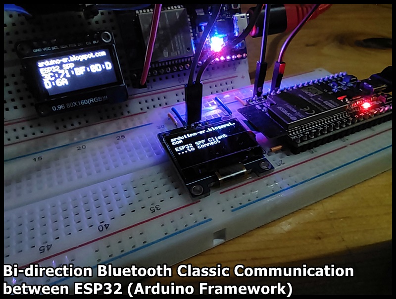
Bi-direction Bluetooth Classic comm. between ESP32 (Arduino framework)
Last post show my exercise of "ESP-32S as Bluetooth classic Server, bi-direction communication with Raspberry Pi/Python". Here is the ESP32 implementation for the Client side, to connect to the ESP32 server in last post.
NodeMCU ESP-32S act as a server (in last post):
It echo what received from bluetooth back to sender, and display on SPI ST7735 display.
ESP32-DevKitC-V4 as client (this post):
Connect to server, forward data from serial, to Bluetooth. Display data from Bluetooth on I2C SSD1306 OLED display.
The code start from ESP32 example of SerialToSerialBTM. But I found that the code SerialBT.connect() always return "true", and prompt "Connected Succesfully!", no matter the device name and MAC address, even no server exist.
To solve it, I implement my bluetooth callback function to double check if ESP_SPP_OPEN_EVT raised. I don't know is it a long time solution, anyway it work in this exercise.
SPPClient_ESP32_ssd1306_20201231b.ino/*
* SPP Client on ESP32
* Display on SSD1306
*/
#include "ssd1306.h"
#include "ssd1306_console.h"
#include "BluetoothSerial.h"
Ssd1306Console console;
BluetoothSerial SerialBT;
String ServerMACadd = "3C:71:BF:0D:DD:6A";
uint8_t ServerMAC[6] = {0x3C, 0x71, 0xBF, 0x0D, 0xDD, 0x6A};
String ServerName = "ESP32_SPP";
char *pin = "1234"; //<- standard pin would be provided by default
bool connected;
bool isSppOpened = false;
/*
.arduino15/packages/esp32/hardware/esp32/1.0.4/libraries/
BluetoothSerial/src/BluetoothSerial.cpp
*/
void btCallback(esp_spp_cb_event_t event, esp_spp_cb_param_t *param){
switch (event)
{
case ESP_SPP_INIT_EVT:
Serial.println("ESP_SPP_INIT_EVT");
break;
case ESP_SPP_SRV_OPEN_EVT://Server connection open
Serial.println("ESP_SPP_SRV_OPEN_EVT");
break;
case ESP_SPP_CLOSE_EVT://Client connection closed
Serial.println("ESP_SPP_CLOSE_EVT");
isSppOpened = false;
break;
case ESP_SPP_CONG_EVT://connection congestion status changed
Serial.println("ESP_SPP_CONG_EVT");
break;
case ESP_SPP_WRITE_EVT://write operation completed
Serial.println("ESP_SPP_WRITE_EVT");
break;
case ESP_SPP_DATA_IND_EVT://connection received data
Serial.println("ESP_SPP_DATA_IND_EVT");
break;
case ESP_SPP_DISCOVERY_COMP_EVT://discovery complete
Serial.println("ESP_SPP_DISCOVERY_COMP_EVT");
break;
case ESP_SPP_OPEN_EVT://Client connection open
Serial.println("ESP_SPP_OPEN_EVT");
isSppOpened = true;
break;
case ESP_SPP_START_EVT://server started
Serial.println("ESP_SPP_START_EVT");
break;
case ESP_SPP_CL_INIT_EVT://client initiated a connection
Serial.println("ESP_SPP_CL_INIT_EVT");
break;
default:
Serial.println("unknown event!");
break;
}
}
static void startupScreen()
{
ssd1306_setFixedFont(ssd1306xled_font6x8);
ssd1306_clearScreen();
ssd1306_printFixed(0, 0, "arduiino-er.blogspot.com", STYLE_BOLD);
ssd1306_printFixed(0, 24, "ESP32 SPP Client", STYLE_NORMAL);
}
void setup()
{
Serial.begin(115200);
Serial.println("\n------ begin ----------------\n");
ssd1306_128x64_i2c_init();
ssd1306_clearScreen();
startupScreen();
delay(500);
Serial.println("- to connect -");
ssd1306_printFixed(0, 32, "...to connect", STYLE_NORMAL);
SerialBT.begin("ESP32_Client", true);
SerialBT.register_callback(btCallback);
//connected = SerialBT.connect(ServerName);
connected = SerialBT.connect(ServerMAC);
/*
* In my trial,
* SerialBT.connect() always return true, even no server exist.
* To solve it, I implemented bluetooth event callback function,
* double varify if ESP_SPP_OPEN_EVT raised.
*/
if(connected) {
Serial.println("SerialBT.connect() == true");
} else {
Serial.println("Failed to connect! Reset to re-try");
Serial.println("SerialBT.connect() == false");
ssd1306_printFixed(0, 32,
"Failed to connect! Reset to re-try", STYLE_NORMAL);
while(true){
}
}
//may be there are some delay to call callback function,
//delay before check
delay(500);
if(isSppOpened == false){
Serial.println("isSppOpened == false");
Serial.println("Reset to re-try");
ssd1306_printFixed(0, 32,
"SPP_OPEN not raised! Reset to re-try", STYLE_NORMAL);
while(true){
}
}
Serial.println("isSppOpened == true");
Serial.println("CONNECTED");
ssd1306_clearScreen();
ssd1306_setFixedFont(ssd1306xled_font6x8);
console.println("CONNECTED:");
}
void loop()
{
if(!isSppOpened){
Serial.println("isSppOpened == false : DISCONNECTED");
Serial.println("Reset to re-connect");
console.println("DISCONNECTED");
console.println("Reset to re-connect");
while(true){
}
}
if (Serial.available()) {
SerialBT.write(Serial.read());
}
if (SerialBT.available()) {
char c = SerialBT.read();
//Serial.write(c);
console.print(c);
}
delay(20);
}
For the setup of SPI ST7735 IPS used on server side, refer to the post "ESP32 display with 0.96" 80x160 SPI ST7735 IPS Display, using TFT_eSPI lib".
For the setup of I2C SSD1306 OLED used on client side, refer to the post "I2C SSD1306 OLED@ESP32 (ESP32-DevKitC-V4), using SSD1306 lib".
Tuesday, December 29, 2020
ESP-32S as Bluetooth classic Server, bi-direction communication with Raspberry Pi/Python
NodeMCU ESP-32S (in Arduino framework) act as a Bluetooth classical (SPP) server:
It echo what received back to sender, and display on SPI ST7735 display.
Also implement callback function to detect esp_spp_cb_event_t.
Python code run on Raspberry Pi, act as GUI Bluetooth classic client, using tkinter/pybluez. Python code refer to: Hello Raspberry Pi - Raspberry Pi/Python as Bluetooth classic client, bi-direction communication with ESP32
Arduino code on ESP32, SPPServer_ESP32.ino.
// ref: Examples > BluetoothSerial > SerialToSerialBT
//with SPI ST735 80x160 IPS Display
#include "BluetoothSerial.h"
#include "esp_bt_device.h"
#include <TFT_eSPI.h> // TFT library
#include <SPI.h>
#if !defined(CONFIG_BT_ENABLED) || !defined(CONFIG_BLUEDROID_ENABLED)
#error Bluetooth is not enabled! Please run `make menuconfig` to and enable it
#endif
BluetoothSerial SerialBT;
TFT_eSPI tft = TFT_eSPI();
const String deviceName = "ESP32_SPP";
String getMAC(){
 const uint8_t* point = esp_bt_dev_get_address();
 String s = "";
 for (int i = 0; i < 6; i++) {
 char str[3];
 sprintf(str, "%02X", (int)point[i]);
 s = s + str;
 if (i < 5){
 s = s+ ":";
 }
 }
 return s;
}
/*
.arduino15/packages/esp32/hardware/esp32/1.0.4/libraries/
BluetoothSerial/src/BluetoothSerial.cpp
 */
void btCallback(esp_spp_cb_event_t event, esp_spp_cb_param_t *param){
 //tft.fillScreen(TFT_BLACK);
 //tft.setCursor(0, 0, 2);
 //tft.setTextSize(1);

 switch (event)
 {
 case ESP_SPP_INIT_EVT:
 Serial.println("ESP_SPP_INIT_EVT");
 //tft.println("ESP_SPP_INIT_EVT");
 break;
 case ESP_SPP_SRV_OPEN_EVT://Server connection open
 Serial.println("ESP_SPP_SRV_OPEN_EVT");
 //tft.println("ESP_SPP_SRV_OPEN_EVT");
 tft.fillScreen(TFT_BLACK);
 tft.setCursor(0, 0, 1);
 tft.setTextSize(1);
 break;
 case ESP_SPP_CLOSE_EVT://Client connection closed
 Serial.println("ESP_SPP_CLOSE_EVT");
 //tft.println("ESP_SPP_CLOSE_EVT");
 startUpScr();
 break;
 case ESP_SPP_CONG_EVT://connection congestion status changed
 Serial.println("ESP_SPP_CONG_EVT");
 //tft.println("ESP_SPP_CONG_EVT");
 break;
 case ESP_SPP_WRITE_EVT://write operation completed
 Serial.println("ESP_SPP_WRITE_EVT");
 //tft.println("ESP_SPP_WRITE_EVT");
 break;
 case ESP_SPP_DATA_IND_EVT://connection received data
 Serial.println("ESP_SPP_DATA_IND_EVT");
 //tft.println("ESP_SPP_DATA_IND_EVT");
 break;
 case ESP_SPP_DISCOVERY_COMP_EVT://discovery complete
 Serial.println("ESP_SPP_DISCOVERY_COMP_EVT");
 //tft.println("ESP_SPP_DISCOVERY_COMP_EVT");
 break;
 case ESP_SPP_OPEN_EVT://Client connection open
 Serial.println("ESP_SPP_OPEN_EVT");
 //tft.println("ESP_SPP_OPEN_EVT");
 break;
 case ESP_SPP_START_EVT://server started
 Serial.println("ESP_SPP_START_EVT");
 //tft.println("ESP_SPP_START_EVT");
 break;
 case ESP_SPP_CL_INIT_EVT://client initiated a connection
 Serial.println("ESP_SPP_CL_INIT_EVT");
 //tft.println("ESP_SPP_CL_INIT_EVT");
 break;
 default:
 Serial.println("unknown event!");
 //tft.println("unknown event!");
 break;
 }
}
void startUpScr(){
 tft.fillScreen(TFT_BLACK);
 tft.setCursor(0, 0, 2);
 tft.setTextSize(1);
 tft.println("arduino-er.blogspot.com");
 tft.println(deviceName);
 tft.setTextFont(1);
 tft.setTextSize(2);
 tft.println(getMAC());
}
void setup() {
 Serial.begin(115200);
 Serial.println("\n---Start---");
 SerialBT.begin(deviceName); //Bluetooth device name

 Serial.println("The device started, now you can pair it with bluetooth!");
 Serial.println("Device Name: " + deviceName);
 Serial.print("BT MAC: ");
 Serial.print(getMAC());
 Serial.println();
 SerialBT.register_callback(btCallback);
 tft.init();
 tft.setRotation(3);
 startUpScr();
}
void loop() {
 if (Serial.available()) {
 SerialBT.write(Serial.read());
 }
 if (SerialBT.available()) {
 char c = SerialBT.read();
 SerialBT.write(c);
 String s = String(c);
 if(tft.getCursorY() >= 80){
 tft.setCursor(0, 0);
 tft.fillScreen(TFT_BLACK);
 }
 tft.print(s);
 }
 delay(20);
}
Sunday, December 27, 2020
ESP32 display with 0.96" 80x160 SPI ST7735 IPS Display, using TFT_eSPI lib
Updated@2021年01月06日, after library updated.
Friday, December 25, 2020
ESP32 receive Bluetooth Classic command from Raspberry Pi/Python, to control Servos.
In my previous posts, I show simple examples of ESP32 Bluetooth Classic serial example, Servo Motor Control and I2C SSD1306 OLED. In this exercise, group three altogether run on ESP32-DevKitC-V4, receive single character command from Raspberry Pi/Python via Bluetooth Classic, control Servo Motors, and display position on 0.96" 128x64 I2C SSD1306 OLED.
Connection:
BTServoServer_20201226.ino
// BTServoServer
#include "BluetoothSerial.h"
#include "esp_bt_device.h"
#include "ssd1306.h"
#include <ESP32Servo.h>
#if !defined(CONFIG_BT_ENABLED) || !defined(CONFIG_BLUEDROID_ENABLED)
#error Bluetooth is not enabled! Please run `make menuconfig` to and enable it
#endif
BluetoothSerial SerialBT;
Servo myservoX; // create servo objects to control a servo
Servo myservoY;
int servoPinX = 18;
int servoPinY = 19;
#define CMD_ORG 'O'
#define CMD_XDEC 'A'
#define CMD_XDEC10 'B'
#define CMD_XINC 'C'
#define CMD_XINC10 'D'
#define CMD_YDEC 'E'
#define CMD_YDEC10 'F'
#define CMD_YINC 'G'
#define CMD_YINC10 'H'
int x = 0;
int y = 0;
void printDeviceAddress() {

 const uint8_t* point = esp_bt_dev_get_address();

 for (int i = 0; i < 6; i++) {

 char str[3];

 sprintf(str, "%02X", (int)point[i]);
 Serial.print(str);

 if (i < 5){
 Serial.print(":");
 }

 }
}
void setup() {
 Serial.begin(115200);
 Serial.println("\n---Start---");
 SerialBT.begin("ESP32test"); //Bluetooth device name

 Serial.println("The device started, now you can pair it with bluetooth!");
 Serial.println("Device Name: ESP32test");
 Serial.print("BT MAC: ");
 printDeviceAddress();
 Serial.println();
 ssd1306_setFixedFont(ssd1306xled_font6x8);
 ssd1306_128x64_i2c_init();
 ssd1306_clearScreen();
 ssd1306_printFixed(0, 8, "BTServoServer", STYLE_BOLD);
 ssd1306_printFixed(0, 40, "arduino-er.blogspot.com", STYLE_BOLD);
 // Allow allocation of all timers
 ESP32PWM::allocateTimer(0);
 ESP32PWM::allocateTimer(1);
 ESP32PWM::allocateTimer(2);
 ESP32PWM::allocateTimer(3);
 myservoX.setPeriodHertz(50); // standard 50 hz servo
 myservoX.attach(servoPinX, 500, 2500); // attaches the servo on pin 18 to the servo object
 myservoY.setPeriodHertz(50); // standard 50 hz servo
 myservoY.attach(servoPinY, 500, 2500);
 myservoX.write(90);
 myservoY.write(90);
}
void loop() {
 if (SerialBT.available()) {
 char cmd = SerialBT.read();
 switch(cmd) {
 case CMD_ORG:
 x = 0;
 y = 0;
 break;
 case CMD_XDEC:
 x--;
 break;
 case CMD_XDEC10:
 x = x-10;
 break;
 case CMD_XINC:
 x++;
 break;
 case CMD_XINC10:
 x = x+10;
 break;
 case CMD_YDEC:
 y--;
 break;
 case CMD_YDEC10:
 y = y-10;
 break;
 case CMD_YINC:
 y++;
 break;
 case CMD_YINC10:
 y = y+10;
 break;
 default:
 Serial.println("unknown command!");
 break;
 }
 if(x < -90)
 x = -90;
 if(x > 90)
 x = 90;
 if(y < -90)
 y = -90;
 if(y > 90)
 y = 90;
 String s = String(x, DEC) + " : " + String(y, DEC) + " ";
 const char* c;
 c = s.c_str();
 Serial.println(s);
 ssd1306_printFixed(0, 25, c, STYLE_NORMAL);
 myservoX.write(x + 90);
 myservoY.write(y + 90);
 delay(200); // wait for the servo to get there
 }
 delay(20);
}
Python code in Raspberry Pi side, refer to my another blog's post: Hello Raspberry Pi - Raspberry Pi/Python remote control ESP32/Servos via Bluetooth Classic
Thursday, December 24, 2020
I2C SSD1306 OLED@ESP32 (ESP32-DevKitC-V4), using SSD1306 lib.
ESP32 (ESP32-DevKitC-V4) run in Arduino framework, to display on 0.96" 128x64/0.91"128x32 OLED with I2C SSD1306 driver, using SSD1306 library.
Install Library:
Search and install ssd1306 library (by Alexey Dynda) via Arduino IDE library manager.
Connection:
ESP32			I2C SSD1306 OLED
(ESP32-DevKitC-V4)
====================================
3V3			VCC
GND			GND
IO22			SCL
IO21			SDA
Save, verify and upload.
Related:
Wednesday, December 23, 2020
ESP32 i2c_scanner
i2c_scanner in Arduino Playground is a very simple sketch scans the I2C-bus for devices. If a device is found, it is reported to the Arduino serial monitor. It can be run on ESP32 to scan your connected I2C device and print its I2C address.
i2c_scanner
 // --------------------------------------
// i2c_scanner
//
// Version 1
// This program (or code that looks like it)
// can be found in many places.
// For example on the Arduino.cc forum.
// The original author is not know.
// Version 2, Juni 2012, Using Arduino 1.0.1
// Adapted to be as simple as possible by Arduino.cc user Krodal
// Version 3, Feb 26 2013
// V3 by louarnold
// Version 4, March 3, 2013, Using Arduino 1.0.3
// by Arduino.cc user Krodal.
// Changes by louarnold removed.
// Scanning addresses changed from 0...127 to 1...119,
// according to the i2c scanner by Nick Gammon
// https://www.gammon.com.au/forum/?id=10896
// Version 5, March 28, 2013
// As version 4, but address scans now to 127.
// A sensor seems to use address 120.
// Version 6, November 27, 2015.
// Added waiting for the Leonardo serial communication.
//
//
// This sketch tests the standard 7-bit addresses
// Devices with higher bit address might not be seen properly.
//
#include <Wire.h>
void setup()
{
 Wire.begin();
 Serial.begin(9600);
 while (!Serial); // Leonardo: wait for serial monitor
 Serial.println("\nI2C Scanner");
}
void loop()
{
 byte error, address;
 int nDevices;
 Serial.println("Scanning...");
 nDevices = 0;
 for(address = 1; address < 127; address++ )
 {
 // The i2c_scanner uses the return value of
 // the Write.endTransmisstion to see if
 // a device did acknowledge to the address.
 Wire.beginTransmission(address);
 error = Wire.endTransmission();
 if (error == 0)
 {
 Serial.print("I2C device found at address 0x");
 if (address<16)
 Serial.print("0");
 Serial.print(address,HEX);
 Serial.println(" !");
 nDevices++;
 }
 else if (error==4)
 {
 Serial.print("Unknown error at address 0x");
 if (address<16)
 Serial.print("0");
 Serial.println(address,HEX);
 }
 }
 if (nDevices == 0)
 Serial.println("No I2C devices found\n");
 else
 Serial.println("done\n");
 delay(5000); // wait 5 seconds for next scan
}
Next:
Tuesday, December 22, 2020
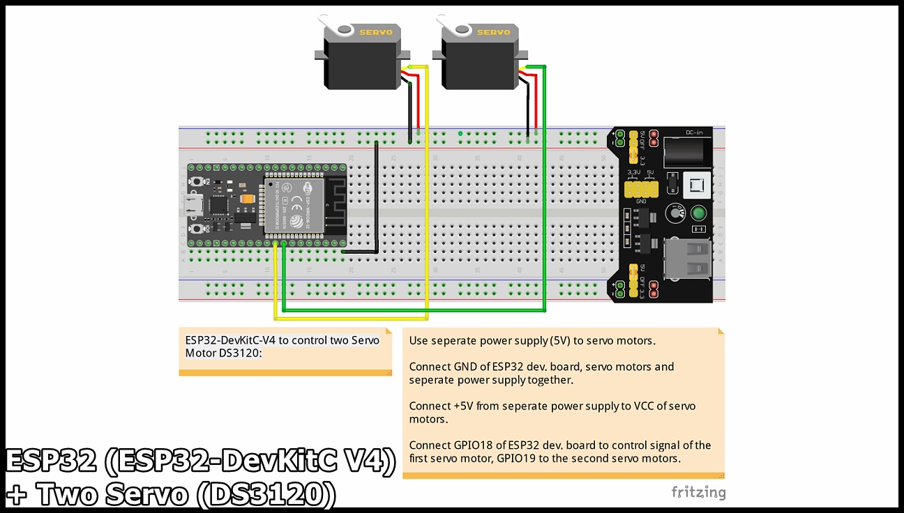
ESP32 (ESP32-DevKitC-V4) to drive Servo Motors using ESP32Servo lib
This example show how to program ESP32 (ESP32-DevKitC-V4) to drive Servo Motors (one SG90/two DS3120) using ESP32Servo lib, using ESP32Servo library.
Drive one SG90 Servo Motor:
Connection:
Install ESP32Servo in Arduino IDE's Library manager.
Open example of ESP32Server > Sweep.
As shown in the video, change min/max to 500/2500.
Sweep_esp32_sg90.ino/* Sweep
Original from ESP32Servo examples Sweep
https://github.com/madhephaestus/ESP32Servo
*/
#include <ESP32Servo.h>
Servo myservo; // create servo object to control a servo
// 16 servo objects can be created on the ESP32
int pos = 0; // variable to store the servo position
// Recommended PWM GPIO pins on the ESP32 include 2,4,12-19,21-23,25-27,32-33
int servoPin = 18;
void setup() {
// Allow allocation of all timers
ESP32PWM::allocateTimer(0);
ESP32PWM::allocateTimer(1);
ESP32PWM::allocateTimer(2);
ESP32PWM::allocateTimer(3);
myservo.setPeriodHertz(50); // standard 50 hz servo
myservo.attach(servoPin, 500, 2500); // attaches the servo on pin 18 to the servo object
// using default min/max of 1000us and 2000us
// different servos may require different min/max settings
// for an accurate 0 to 180 sweep
}
void loop() {
for (pos = 0; pos <= 180; pos += 1) { // goes from 0 degrees to 180 degrees
// in steps of 1 degree
myservo.write(pos); // tell servo to go to position in variable 'pos'
delay(15); // waits 15ms for the servo to reach the position
}
for (pos = 180; pos >= 0; pos -= 1) { // goes from 180 degrees to 0 degrees
myservo.write(pos); // tell servo to go to position in variable 'pos'
delay(15); // waits 15ms for the servo to reach the position
}
}
Drive two DS3120 Servo Motor:
Connection:
modify the code to add one more Servo:
Sweep_esp32_two_ds3120.ino
/* Sweep
Original from ESP32Servo examples Sweep
https://github.com/madhephaestus/ESP32Servo
 */
#include <ESP32Servo.h>
Servo myservo; // create servo object to control a servo
Servo myservo2;
// 16 servo objects can be created on the ESP32
int pos = 0; // variable to store the servo position
// Recommended PWM GPIO pins on the ESP32 include 2,4,12-19,21-23,25-27,32-33
int servoPin = 18;
int servoPin2 = 19;
void setup() {
	// Allow allocation of all timers
	ESP32PWM::allocateTimer(0);
	ESP32PWM::allocateTimer(1);
	ESP32PWM::allocateTimer(2);
	ESP32PWM::allocateTimer(3);
	myservo.setPeriodHertz(50); // standard 50 hz servo
	myservo.attach(servoPin, 500, 2500); // attaches the servo on pin 18 to the servo object
	myservo2.setPeriodHertz(50); // standard 50 hz servo
	myservo2.attach(servoPin2, 500, 2500);
	// using default min/max of 1000us and 2000us
	// different servos may require different min/max settings
	// for an accurate 0 to 180 sweep
}
void loop() {
	for (pos = 0; pos <= 180; pos += 1) { // goes from 0 degrees to 180 degrees
		// in steps of 1 degree
		myservo.write(pos); // tell servo to go to position in variable 'pos'
		myservo2.write(pos);
		delay(15); // waits 15ms for the servo to reach the position
	}
	for (pos = 180; pos >= 0; pos -= 1) { // goes from 180 degrees to 0 degrees
		myservo.write(pos); // tell servo to go to position in variable 'pos'
		myservo2.write(pos);
		delay(15); // waits 15ms for the servo to reach the position
	}
}
Next:
Sunday, December 20, 2020
ESP32: Get chip info
#include <Esp.h>
void setup() {
 Serial.begin(115200);
 Serial.printf("\n\n---Start---\n");
 Serial.print("Chip Revision: ");
 Serial.print(ESP.getChipRevision());
 Serial.printf("\nCpuFreqMHz(): %lu", (unsigned long)ESP.getCpuFreqMHz());
 Serial.printf("\nSdkVersion: %s", ESP.getSdkVersion());
 Serial.printf("\nFlashChipSize: %lu", (unsigned long)ESP.getFlashChipSize());
}
void loop() {

}
Saturday, December 19, 2020
ESP32 Bluetooth serial example
It's a simple example of ESP32 Bluetooth serial communication, run on ESP32-DevKitC V4.
The video show how it run, to communicate with Python/Raspberry Pi. The Python code is in my another blog: HelloRaspberryPi - Python (on Raspberry Pi) Bluetooth communicate with ESP32 SerialToSerialBT, using pybluez.
To make the ESP32 examples appear in examples list, you have to choose board of ESP32 first. It's ESP32 Wrover Module in may case.
The example available in Arduino IDE MENU > File > Examples > Bluetooth Serial (under Examples for Wrover Module) > SerialToSerialBT.
// ref: Examples > BluetoothSerial > SerialToSerialBT
#include "BluetoothSerial.h"
#include "esp_bt_device.h"
#if !defined(CONFIG_BT_ENABLED) || !defined(CONFIG_BLUEDROID_ENABLED)
#error Bluetooth is not enabled! Please run `make menuconfig` to and enable it
#endif
BluetoothSerial SerialBT;
void printDeviceAddress() {

 const uint8_t* point = esp_bt_dev_get_address();

 for (int i = 0; i < 6; i++) {

 char str[3];

 sprintf(str, "%02X", (int)point[i]);
 Serial.print(str);

 if (i < 5){
 Serial.print(":");
 }

 }
}
void setup() {
 Serial.begin(115200);
 Serial.println("\n---Start---");
 SerialBT.begin("ESP32test"); //Bluetooth device name

 Serial.println("The device started, now you can pair it with bluetooth!");
 Serial.println("Device Name: ESP32test");
 Serial.print("BT MAC: ");
 printDeviceAddress();
 Serial.println();
}
void loop() {
 if (Serial.available()) {
 SerialBT.write(Serial.read());
 }
 if (SerialBT.available()) {
 Serial.write(SerialBT.read());
 }
 delay(20);
}
Friday, December 18, 2020
ESP32-DevKitC V4 - ESP32-WROVER-E module, with ESP32-D0WD-V3 embedded
- ESP32-WROOM-32E
- ESP32-WROOM-32UE
- ESP32-WROOM-32D
- ESP32-WROOM-32U
- ESP32-SOLO-1
- ESP32-WROVER-E
- ESP32-WROVER-IE
Saturday, September 5, 2020
Program ESP32-CAM using FTDI adapter
This video show how to program AI-Thinker ESP32-CAM in Arduino IDE (with ESP32 Core), using FTDI adapter.
It have no USB interface on board, and also no button for downloading firmware. So I have to use a FTDI adapter, and a wire to program it.
The FTDI adapter have option to select 3V3 or 5V for VCC. Somebody suggest using 3V3, somebody else suggest 5V. In my case, 5V seem more stable, so I select option of 5V, and connect its VCC pin to ESP32's 5V pin. FTDI's GND to ESP32's GND.
To program ESP32-CAM, using a wire to short circuit between ESP32's GPIO0 and GND.
ESP32's UOT to FTDI RX.
ESP32's UOR to FTDI TX.
Make sure ESP32 is installed in Arduino IDE. To setup ESP32 on Arduino IDE, refer Install ESP32/ESP8266 to Arduino IDE on Ubuntu 20.04, with setup Pythton & serial.
Select board of AI Thinker ESP32-CAM.
Select the USB port connected to your ESP32-CAM.
Open Example > ESP32 > Camera > CameraWebServer
Modify the code:
Select camera model of
CAMERA_MODEL_AI_THINKER,
and change ssid and password for your
WiFi network.
Save as another new file. Verify and Upload to ESP32.
After uploaded,
Un-plug USB from FTDI adapter (power-off).
Remove
the wire between GPIO0 and GND.
Re-plug USB to FTDI adapter (power-on),
to run the ESP32-CAM.
Open Arduino IDE's Serial Monitor and set Baud Rate to 115200.
After
ESP32-CAM connect to WiFi network, mark down the IP address.
Use another device, PC, phone or table..., connect to the same WiFi
network.
Open browser to visit the IP shown in Serial Monitor.
Reference:
~
AI-Thinker's ESP32-CAM page
(in Chinese)
Remark:
Monday, August 24, 2020
millis() overflow? BlinkWithoutDelay question?
Normal if we want to run some code in fixed interval, we will use the following pattern:
void loop() {
	// check if the fixed interval reached
	unsigned long currentMillis = millis();
	if (currentMillis - previousMillis >= interval) {
		//do something in fixed interval
		//...


	}
}
void setup() {
 Serial.begin(9600);
 while (!Serial) {
 } // wait for serial port to connect.
 unsigned long i =0;
 unsigned long j = i-1;
 unsigned long k = j+1000;

 Serial.print("i = ");
 Serial.println(i);
 Serial.print("j = ");
 Serial.println(j);
 Serial.print("k = ");
 Serial.println(k);
 Serial.print("(k > j) : ");
 Serial.println((k > j) ? "true" : "false");
 Serial.print("k-j : ");
 Serial.println(k-j);

 Serial.print("((k-j) >= 1000) : ");
 Serial.println(((k-j) >= 1000) ? "true" : "false");

}
void loop() {
 // put your main code here, to run repeatedly:
}
Sunday, August 16, 2020
NodeMCU (ESP8266) + 1.44" 128x128 TFT with ST7735 SPI driver (KMR1441_SPI V2)
This video show how to driver 1.44" 128x128 TFT with ST7735 SPI driver (KMR1441_SPI V2) with NodeMCU (ESP8266) using ssd1306 library. Using Arduino IDE.
- In Arduino IDE, open library manager, search ST7735, and install ssd1306 library.
- Open Example > ssd1306 > demos > st7735_demo
- Connect ESP8266 to LCD
ESP8266LCD
===================
3V3VCC
GND GND
D1A0 (D/C)
D2CS (CS)
RXRESET (RES)
D7SDA (DIN)
D5SCK (CLK)
LED (Open in my test)
Thursday, July 23, 2020
ATGM336H-5N/ESP32, read GPS position using TinyGPS++
TinyGPS++ is a new Arduino library for parsing NMEA data streams provided by GPS modules. To install this library, download here, unzip the archive into the Arduino “libraries” folder, and restart Arduino. You should rename the folder “TinyGPSPlus”.
/*
Connection between ESP32 and ATGM336H-5N:
ESP32		ATGM336H-5N
-----------------------
VCC		VCC
GND		GND
16 (RX)		TX
17 (TX)		RX
*/
static const int RXPin = 16, TXPin = 17;
static const uint32_t GPSBaud = 9600;
Wednesday, July 22, 2020
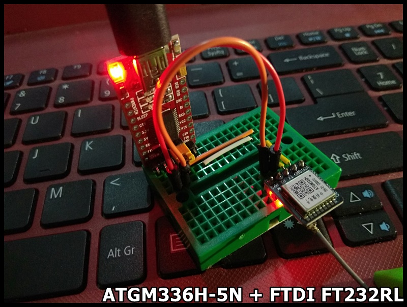
ATGM336H-5N, GNSS Module support BDS (BeiDou Navigation Satellite System)
The BeiDou Navigation Satellite System (BDS) (北斗卫星导航系统) is a Chinese satellite navigation system.
To first test the ATGM336H-5N module. I install Ublox's u-center on Windows, connect the module using a FTDI FT232RL USB to Serial board.
Connection between ATGM336H-5N and FT232RL
VCC(ATGM336H-5N) <---> VCC(FT232RL)
GND(ATGM336H-5N) <---> GND(FT232RL)
TX(ATGM336H-5N) <---> RX(FT232RL)
RX(ATGM336H-5N) <---> TX(FT232RL)
Install and run Ublox - u-center (GNSS evaluation software for Windows)
Next: