Electric Motor Control
Electric Motor Control
10th Edition
ISBN: 9781133702818
Author: Herman
Publisher: CENGAGE L
expand_more
expand_more
format_list_bulleted
Bartleby Related Questions Icon
Related questions
Question
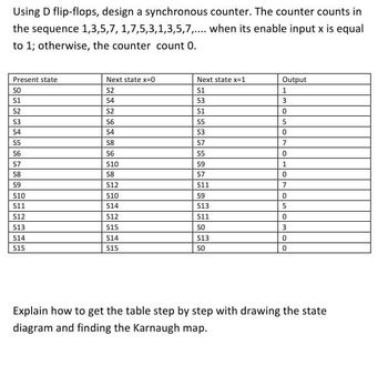
Transcribed Image Text:Using D flip-flops, design a synchronous counter. The counter counts in
the sequence 1,3,5,7, 1,7,5,3,1,3,5,7,.... when its enable input x is equal
to 1; otherwise, the counter count 0.
Present state
Next state x=0
Next state x=1
Output
SO
52
S1
1
S1
54
53
3
52
53
S2
56
51
0
5ドル
5
54
S4
53
0
55
58
57
7
56
56
55
0
57
S10
59
1
58
58
S7
0
59
S12
S11
7
10ドル
10ドル
59
0
11ドル
14ドル
13ドル
5
12ドル
S12
11ドル
0
513
15ドル
SO
3
S14
14ドル
S13
0
15ドル
515
SO
0
Explain how to get the table step by step with drawing the state
diagram and finding the Karnaugh map.
Expert Solution
Check MarkThis question has been solved!
Explore an expertly crafted, step-by-step solution for a thorough understanding of key concepts.
bartleby
Step by stepSolved in 2 steps with 5 images
Knowledge Booster
Background pattern image
Similar questions
- a) Design a single-digit decade counter that counts from 0 to 9 and repeats. The single-digit decade counter should be built by a cascaded synchronous binary counter (74LS163) and other basic logic gates. Simulate the complete counter circuit by OrCAD and PSPICE. Capture the circuit schematic and the simulated waveform. (Define the simulation timings for at least one full counting cycle from 0 to 9 and back to 0.) (Hint: Use the DigClock input from the SOURCE as shown below and setup the CLK ONTIME and OFFTIME accordingly for the clock source.) 1/6 Pat DigClock Part List OFFTIME = SuS DSTM1 ONTIME = DELAY= STARTVAL = 0 OPPVAL = 1 Sus EUK FleStim AC Lbrajes Design Cache b) Read the specification of 74LS47 (BCD-to-7-Segment Decoder shown in Appendix) to see how the logic IC operates to drive a 7-segment LED display. Draw the circuit connection of the decade counter in (a) and the decoder to display the count value on the 7-segment LED display. Further explain why common anode...arrow_forward(c) For each of the following parts, fill in the respective row of the timing diagram shown in Figure 5. (i) Find the input for a rising-edge-triggered D flip-flop that would produce the output Q as shown in Figure 5. (ii) Find the input for a rising-edge-triggered T flip-flop that would produce the output Q as shown in Figure 5. Clock D Figure 5arrow_forwarda) Design a single-digit decade counter that counts from 0 to 9 and repeats. The single-digit decade counter should be built by a cascaded synchronous binary counter (74LS163) and other basic logic gates. Simulate thecomplete counter circuit by OrCAD and PSPICE. Capture the circuit schematic and the simulated waveform.(Define the simulation timings for at least one full counting cycle from 0 to 9 and back to 0.)(Hint: Use the DigClock input from the SOURCE as shown below and setup the CLK ONTIME and OFFTIME accordingly for the clock source.)arrow_forward
- Design a 3-bit synchronous counter, which counts in the sequence: 001, 011, 010, 110, 111, 101, 100 (repeat) 001, ... Draw the schematic of the design with three flip-flops and combinational logics.arrow_forward(d) Figure 6 shows the diagram of a 3-bit ripple counter. Assume Qo = Q1 = Q2 = 0 at t = 0, and assume each flip-flop has a delay of 1 ns from the clock input to the Q output. Fill in Qo, Q1, and Q2 of the timing diagram (shown in Figure 7). Flip-flop Q1 will be triggered when Qo changes from 0 to 1. %3D 3 Qo Q2 T T Clock- Figure 6 Clock 10 15 20 25 30 35 40 45 50 Figure 7arrow_forwardI need a solution very quickly withinarrow_forward
- Construct a synchronous 3-bit Up/Down counter with irregular sequence by using J-K flip-flops. The state diagram is shown below.arrow_forwardDesign a combinational circuit using multiplexer for a car chime based on thefollowing system: A car chime or bell will sound if the output of the logic circuit(X) is set to a logic ‘1’. The chime is to be sounded for either of the followingconditions:• if the headlights are left on when the engine is turned off and• if the engine is off and the key is in the ignition when the door is opened.Use the following input names and nomenclature in the design process:• ‘E’ – Engine. ‘1’ if the engine is ON and ‘0’ if the engine is OFF• ‘L’ – Lights. ‘1’ if the lights are ON and ‘0’ if the lights are OFF• ‘K’ – Key. ‘1’ if the key is in the ignition and ‘0’ if the key is not in the ignition• ‘D’ – Door. ‘1’ the door is open and ‘0’ if the door is closed• ‘X’ – Output to Chime. ‘1’ is chime is ON and ‘0’ if chime is OFFarrow_forward2- Using JK Flip flops, a 2-bit counter will be designed that will count down ((11-10-01-00) when the input is "0") and the random sequence given when the input is "1" (00-01-11-10). a) Construct the state table for the sequential circuit. b) Obtain the simplified input equations for flip-flops. c) Draw the logic circuit for the 2-bit counter.arrow_forward
- Q6. For the following state graph, construct a transition table. Then, give the timing diagram for the input sequence X = 101001. Assume X changes midway between the falling and rising edges of the clock, and that the flip-flops are falling-edge triggered. What is the correct output sequence? So S3arrow_forwardQ6/ Design 4 bits up- down counter. Using JK-flip flop.arrow_forwardA counter circuit is shown in Figure Q4(b). Redesign this counter using two T flip-flops and logic gates. (b) QB ac D Flip-flop D Flip-flop D Flip-flop B CIK CIk CIK Clock Clear Clear Clear Clear Figure Q4(b) 10arrow_forward
arrow_back_ios
SEE MORE QUESTIONS
arrow_forward_ios
Recommended textbooks for you
- Text book image
Text book image