Introductory Circuit Analysis (13th Edition)
Introductory Circuit Analysis (13th Edition)
13th Edition
ISBN: 9780133923605
Author: Robert L. Boylestad
Publisher: PEARSON
expand_more
expand_more
format_list_bulleted
Bartleby Related Questions Icon
Related questions
Question
Written Answer Needed
Correct one
Transcribed Image Text:Question
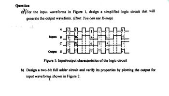
a) (For the input waveforms in Figure 1, design a simplified logic circuit that will
generate the output waveform. (Hint: You can use K-map)
Inputs B
Output X
Figure 1: Input/output characteristics of the logic circuit
b) Design a two-bit full adder circuit and verify its properties by plotting the output for
input waveforms shown in Figure 2.
Expert Solution
Check MarkThis question has been solved!
Explore an expertly crafted, step-by-step solution for a thorough understanding of key concepts.
bartleby
Step by stepSolved in 2 steps with 2 images
Knowledge Booster
Background pattern image
Similar questions
- Q2/A) Design 8x1 multiplexer using 2x1 multiplexer? Q2 B)Simplify the Logic circuit shown below using K-map then draw the Simplified circuit? Q2/C) design logic block diagram for adding 12 to 5 using full adder showing the input for each adder?arrow_forwardH.W: Reduce the combinational logic circuit in Figure below to a minimum form.arrow_forwardMention Written Answer Needed Correct onearrow_forward
- (b) Figure Q2(b) shows input waveforms of A, B and C. Draw the logic circuit that will generate the output waveform X. A Inputs B Output X Figure Q2(b) : Input and output waveformsarrow_forwardi need the answer quicklyarrow_forwardFor the input waveforms in Figure , what logic circuit will generate the output waveform shown? Explain in detail for each. Inputs B Output X Inputs B Output Xarrow_forward
- 2.31 For the timing diagram in Figure P2.3, synthesis the function f(x1, x2,x3) in the simplest sum-of-products form. X2 Time Figure P2.3 A timing diagram representing a logic functionarrow_forwardDesign a logic circuit for decoder that accepts 3-bit input and displays alphabet "048" at the seven- segment as illustrated at Figure 1 (a). The input-output mapping shown in Table 1 (a). Refer Figure 1(b) and Figure 1(c) for seven-segment display format showing arrangements of segments using common anode connection. Show each steps clearly to produce the expressions and required design. [Rekabentuk litar logik untuk penyahkod yang menerima input 3-bit dan paparkan abjad "048" di tujuh-segmen seperti digambarkan pada Rajah 1(a). Pemetaan masukan-keluaran ditunjukkan dalam Jadual 1(a). Rujuk Rajah 1(b) and Rajah 1(c) untuk format paparan tujuh-segmen yang menunjukkan susunan segmen menngunakan sambungan 'common anode'. Tunjukkan setiap langkah dengan jelas untuk menghasilkan ungkapan dan reka bentuk yang dikehendaki.] Xs X6 X7 DECODER Figure 1(a) [Rajah 1(a)] a b с d e f g a 80123456789 Figure 1(c) [Rajah 1(c)] g Figure 1 (b) [Rajah 1(b)] b с DParrow_forwardI need to solve it quicklyarrow_forward
- What is a TTL circuit? What are their main characteristics? (Input voltage and current, output voltage and current, Vcc, ...)arrow_forwardY=f(A,B,C)=(0,4,5)+don't care(2)arrow_forwardQ1.B. Explain output control by voltage cancellation in a single-phase inverter. What are the advantages over square wave operation?arrow_forward
arrow_back_ios
SEE MORE QUESTIONS
arrow_forward_ios
Recommended textbooks for you
- Text book imageIntroductory Circuit Analysis (13th Edition)Electrical EngineeringISBN:9780133923605Author:Robert L. BoylestadPublisher:PEARSONText book imageDelmar's Standard Textbook Of ElectricityElectrical EngineeringISBN:9781337900348Author:Stephen L. HermanPublisher:Cengage LearningText book imageProgrammable Logic ControllersElectrical EngineeringISBN:9780073373843Author:Frank D. PetruzellaPublisher:McGraw-Hill Education
- Text book imageFundamentals of Electric CircuitsElectrical EngineeringISBN:9780078028229Author:Charles K Alexander, Matthew SadikuPublisher:McGraw-Hill EducationText book imageElectric Circuits. (11th Edition)Electrical EngineeringISBN:9780134746968Author:James W. Nilsson, Susan RiedelPublisher:PEARSONText book imageEngineering ElectromagneticsElectrical EngineeringISBN:9780078028151Author:Hayt, William H. (william Hart), Jr, BUCK, John A.Publisher:Mcgraw-hill Education,
Text book image
Introductory Circuit Analysis (13th Edition)
Electrical Engineering
ISBN:9780133923605
Author:Robert L. Boylestad
Publisher:PEARSON
Text book image
Delmar's Standard Textbook Of Electricity
Electrical Engineering
ISBN:9781337900348
Author:Stephen L. Herman
Publisher:Cengage Learning
Text book image
Programmable Logic Controllers
Electrical Engineering
ISBN:9780073373843
Author:Frank D. Petruzella
Publisher:McGraw-Hill Education
Text book image
Fundamentals of Electric Circuits
Electrical Engineering
ISBN:9780078028229
Author:Charles K Alexander, Matthew Sadiku
Publisher:McGraw-Hill Education
Text book image
Electric Circuits. (11th Edition)
Electrical Engineering
ISBN:9780134746968
Author:James W. Nilsson, Susan Riedel
Publisher:PEARSON
Text book image
Engineering Electromagnetics
Electrical Engineering
ISBN:9780078028151
Author:Hayt, William H. (william Hart), Jr, BUCK, John A.
Publisher:Mcgraw-hill Education,