Introductory Circuit Analysis (13th Edition)
Introductory Circuit Analysis (13th Edition)
13th Edition
ISBN: 9780133923605
Author: Robert L. Boylestad
Publisher: PEARSON
expand_more
expand_more
format_list_bulleted
Bartleby Related Questions Icon
Related questions
Question
help with some explanation
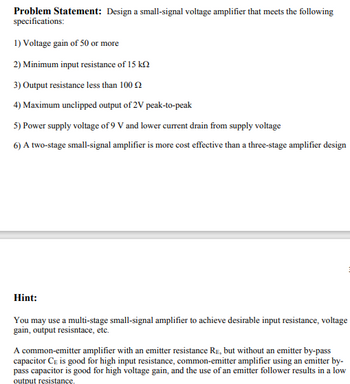
Transcribed Image Text:Problem Statement: Design a small-signal voltage amplifier that meets the following
specifications:
1) Voltage gain of 50 or more
2) Minimum input resistance of 15 k
3) Output resistance less than 100
4) Maximum unclipped output of 2V peak-to-peak
5) Power supply voltage of 9 V and lower current drain from supply voltage
6) A two-stage small-signal amplifier is more cost effective than a three-stage amplifier design
Hint:
You may use a multi-stage small-signal amplifier to achieve desirable input resistance, voltage
gain, output resisntace, etc.
A common-emitter amplifier with an emitter resistance RE, but without an emitter by-pass
capacitor CE is good for high input resistance, common-emitter amplifier using an emitter by-
pass capacitor is good for high voltage gain, and the use of an emitter follower results in a low
output resistance.
Expert Solution
Check MarkThis question has been solved!
Explore an expertly crafted, step-by-step solution for a thorough understanding of key concepts.
bartleby
Step by stepSolved in 2 steps with 8 images
Knowledge Booster
Background pattern image
Similar questions
- 6) Consider the following multistage amplifier. Draw the corresponding small signal model. Label, Vin, Vo1 and Vo. Do NOT make any approximations. Do NOT perform small signal analysis with this model. Just draw the small signal model. Show your work! Vin Vcc malli Q1 Re1 Vo1 Vcc ww1. Rc2 Q2 Re2 Voarrow_forward(1) Describe in detail the relative advantages of Class A and Class B amplifiers. In what types of circuits would Class B be advantageous over Class A (1I) With the aid of signal diagrams, describe two forms of distortion you would expect to observe on an output signal of a Class B amplifier. (III) Describe in circuit terms the advantages of a Class AB amplifier.arrow_forwardPlease solve with work shown. Will upvotearrow_forward
- II.The following figure shows a class AB amplifier. (a) Determine the parameters of dc VB (Q1), VB (Q2), VE, ICQ, VCEQ (Q1), VCEQ (Q2). (b) For a 5-Vrms input, determine the power that is provided to the load resistor, and (c) Draw the output signal +Vcc +9 V 1.0kn D: R 5.0 V rms R2 10 kN -Vecarrow_forwarda) List down TWO (2) types of distortion occurs in practical amplifier operation and briefly explain each of them. b) () Discuss THREE (3) characteristics of a Class A power amplifier. (ii) Discuss THREE (3) characteristics of a Class B power amplifier. (iii) List down THREE (3) advantages of class B power amplifier as compared with class A power amplifier's operation.arrow_forwardThe figure below shows a direct coupled two-stage amplifier. Determine. (i) d.c. voltages for both stages (VB1, VB2, Vc1, Vc2, VE1 and VE2. voltage gain of each stage and overall voltage gain.arrow_forward
- The transistor parameters for the circuit in Figure are B, =B2 = 100, VBE1on) = VBE2ton) = 0.7 V, and %3D VA1 =VA2 =0.Find the small signal voltage gain Av = vo/vs. (Note that V-=0.026 V) Vcc=9 V Rib Q1 Vs 1 ko -Ro 20 V 100 Q -wwarrow_forwardDraw a n-p-n transistor connected in circuit common base (CB).Draw the input current-voltage characteristic, the output current-voltage characteristicsand the graph giving dependence of the output current as function of the input current.Define the amplification gain of this circuit.arrow_forwardWhy are the two circuits called inverting and non-inverting amplifier, respectively?arrow_forward
arrow_back_ios
SEE MORE QUESTIONS
arrow_forward_ios
Recommended textbooks for you
- Text book imageIntroductory Circuit Analysis (13th Edition)Electrical EngineeringISBN:9780133923605Author:Robert L. BoylestadPublisher:PEARSONText book imageDelmar's Standard Textbook Of ElectricityElectrical EngineeringISBN:9781337900348Author:Stephen L. HermanPublisher:Cengage LearningText book imageProgrammable Logic ControllersElectrical EngineeringISBN:9780073373843Author:Frank D. PetruzellaPublisher:McGraw-Hill Education
- Text book imageFundamentals of Electric CircuitsElectrical EngineeringISBN:9780078028229Author:Charles K Alexander, Matthew SadikuPublisher:McGraw-Hill EducationText book imageElectric Circuits. (11th Edition)Electrical EngineeringISBN:9780134746968Author:James W. Nilsson, Susan RiedelPublisher:PEARSONText book imageEngineering ElectromagneticsElectrical EngineeringISBN:9780078028151Author:Hayt, William H. (william Hart), Jr, BUCK, John A.Publisher:Mcgraw-hill Education,
Text book image
Introductory Circuit Analysis (13th Edition)
Electrical Engineering
ISBN:9780133923605
Author:Robert L. Boylestad
Publisher:PEARSON
Text book image
Delmar's Standard Textbook Of Electricity
Electrical Engineering
ISBN:9781337900348
Author:Stephen L. Herman
Publisher:Cengage Learning
Text book image
Programmable Logic Controllers
Electrical Engineering
ISBN:9780073373843
Author:Frank D. Petruzella
Publisher:McGraw-Hill Education
Text book image
Fundamentals of Electric Circuits
Electrical Engineering
ISBN:9780078028229
Author:Charles K Alexander, Matthew Sadiku
Publisher:McGraw-Hill Education
Text book image
Electric Circuits. (11th Edition)
Electrical Engineering
ISBN:9780134746968
Author:James W. Nilsson, Susan Riedel
Publisher:PEARSON
Text book image
Engineering Electromagnetics
Electrical Engineering
ISBN:9780078028151
Author:Hayt, William H. (william Hart), Jr, BUCK, John A.
Publisher:Mcgraw-hill Education,