C++ Programming: From Problem Analysis to Program Design
C++ Programming: From Problem Analysis to Program Design
8th Edition
ISBN: 9781337102087
Author: D. S. Malik
Publisher: Cengage Learning
expand_more
expand_more
format_list_bulleted
Bartleby Related Questions Icon
Related questions
Question
THIS IS NOT A GRADING ASSIGNMENT:
Please only do lab 2.2 (bottom part of the first picture)
For that Lab 2.2 do:
*Part 1 (do the CODE, that's super important I need it)
*Part 2
*Part 3
I also attached Section 2.5.2 which is part of the step 1 so you can read what is it about.
Thank you!
Transcribed Image Text:2.5.2 Subroutines and Macros
Structured Programming can be achieved in assembly source files by using subroutines and
macros. Subroutines and Macros are used to represent tasks that needs to be performed repeatedly
during program execution. Tin execution time or in total memory used by the generated code;
these are known as time and space complexity. A Subroutine exists as one section of code, which
is called by the program from different points during execution, thus it achieved saving in memory
usage at the expense of the overhead execution time associated with the calling and return from
the subroutine. A Macro is defined to the assembler using directive "MACRO" as a block of code
to be included at each reference throughout the program. Macros will produce larger code requiring
more memory, but they require less execution time. In summary, the use of subroutines improves
the space complexity of the implemented task while macros improve its time complexity.
Subroutines are called using the Long Call (LCALL) or the Absolute Call (ACALL) instructions
"LCALL" is a 3-byte instruction; the first byte is the operation code, the second and third bytes
are used for address of the target subroutine which can be located anywhere within the 64K byte
code memory address space. "ACALL" is a 2-byte subroutine call instruction; 11 bits are used for
address within 2K-byte range from the calling PC location. The one-byte length difference
between the two instructions might become handy in low-cost embedded system design due to the
limited size of code memory. The same applies to the SJMP, JMP, AJMP, and LJMP instructions.
The four instructions vary in length from one byte to three bytes and can accommodate different
range branching within the program. When a subroutine is called, control is transferred to that
subroutine location through the following Processor action sequence:
69
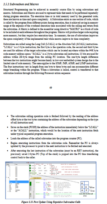
⚫ The subroutine calling operation code is fetched followed by the reading of the address
offset byte or the two bytes containing the address of the subroutine depending on the type
of call instruction used.
• Saves on the stack (PUSH) the address of the instruction immediately below the "LCALL"
or the "ACALL" instruction, which would be the location of the next instruction fetch
under typical sequential program execution.
• Loads the address of the called subroutine into the program counter (PC).
• Begins executing instructions form the subroutine code. Remember the PC is always
updated by the processor to point to the next instruction to be fetched and executed.
• After executing the last instruction of the subroutine (must be an RET instruction), the
previously saved 2-bytes PC (Top of the stack) is popped into the PC thus transferring
control back to the caller.
Figure 2.25 Port Update Using Repetitive Subroutine Calls
06
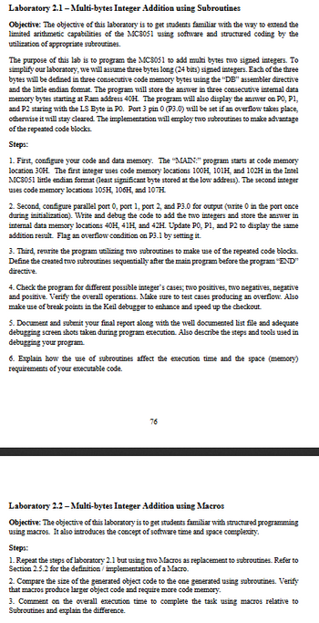
Transcribed Image Text:Laboratory 2.1-Multi-bytes Integer Addition using Subroutines
Objective: The objective of this laboratory is to get students familiar with the way to extend the
limited arithmetic capabilities of the MC8051 using software and structured coding by the
utilization of appropriate subroutines.
The purpose of this lab is to program the MC8051 to add multi bytes two signed integers. To
simplify our laboratory, we will assume three bytes long (24 bits) signed integers. Each of the three
bytes will be defined in three consecutive code memory bytes using the "DB" assembler directive
and the little endian format. The program will store the answer in three consecutive internal data
memory bytes starting at Ram address 40H. The program will also display the answer on PO, P1,
and P2 staring with the LS Byte in P0. Port 3 pin 0 (P3.0) will be set if an overflow takes place,
otherwise it will stay cleared. The implementation will employ two subroutines to make advantage
of the repeated code blocks.
Steps:
1. First, configure your code and data memory. The "MAIN:" program starts at code memory
location 30H. The first integer uses code memory locations 100H, 101H, and 102H in the Intel
MC8051 little endian format (least significant byte stored at the low address). The second integer
uses code memory locations 105H, 106H, and 107H.
2. Second, configure parallel port 0, port 1, port 2, and P3.0 for output (write 0 in the port once
during initialization). Write and debug the code to add the two integers and store the answer in
internal data memory locations 40H, 41H, and 42H. Update P0, P1, and P2 to display the same
addition result. Flag an overflow condition on P3.1 by setting it.
3. Third, rewrite the program utilizing two subroutines to make use of the repeated code blocks.
Define the created two subroutines sequentially after the main program before the program "END"
directive.
4. Check the program for different possible integer's cases; two positives, two negatives, negative
and positive. Verify the overall operations. Make sure to test cases producing an overflow. Also
make use of break points in the Keil debugger to enhance and speed up the checkout.
5. Document and submit your final report along with the well documented list file and adequate
debugging screen shots taken during program execution. Also describe the steps and tools used in
debugging your program.
6. Explain how the use of subroutines affect the execution time and the space (memory)
requirements of your executable code.
76
Laboratory 2.2-Multi-bytes Integer Addition using Macros
Objective: The objective of this laboratory is to get students familiar with structured programming
using macros. It also introduces the concept of software time and space complexity.
Steps:
1. Repeat the steps of laboratory 2.1 but using two Macros as replacement to subroutines. Refer to
Section 2.5.2 for the definition/implementation of a Macro.
2. Compare the size of the generated object code to the one generated using subroutines. Verify
that macros produce larger object code and require more code memory.
3. Comment on the overall execution time to complete the task using macros relative to
Subroutines and explain the difference.
Expert Solution
Check MarkThis question has been solved!
Explore an expertly crafted, step-by-step solution for a thorough understanding of key concepts.
bartleby
Step by stepSolved in 2 steps
Knowledge Booster
Background pattern image
Similar questions
- (Practice) State whether the following are valid function names and if so, whether they’re mnemonic names that convey some idea of the function’s purpose. If they are invalid names, state why. powerdensity m1234 newamp 1234 abcd total tangent absval computed b34a 34ab volts$ a2B3 while minVal sine $sine cosine speed netdistance sum return stackarrow_forward(Practice) Write a C++ program that adds equivalent elements of the two-dimensional arrays named first and second. Both arrays should have two rows and three columns. For example, element [1][2] of the resulting array should be the sum of first [1][2]andsecond[1][2]. The first and second arrays should be initialized as follows: first second 16 18 23 24 52 77 54 9111 16 19 59arrow_forward(Practice) Although the total number of bytes varies from computer to computer, memory sizes of millions and billions of bytes are common. In computer language, the letter M representsthe number 1,048,576, which is 2 raised to the 20th power, and G represents 1,073,741,824, which is 2 raised to the 30th power. Therefore, a memory size of 4 MB is really 4 times 1,048,576 (4,194,304 bytes), and a memory size of 2 GB is really 2 times 1,073,741,824 (2,147,483,648 bytes). Using this information, calculate the actual number of bytes in the following: a. A memory containing 512 MB b. A memory consisting of 512 MB words, where each word consists of 2 bytes c. A memory consisting of 512 MB words, where each word consists of 4 bytes d. A thumb drive that specifies 2 GB e. A disk that specifies 4 GB f. A disk that specifies 8 GBarrow_forward
- (Computation) Among other applications, Pascal’s triangle (see Figure 7.22) provides a means of determining the number of possible combinations of n things taken r at a time. For example, the number of possible combinations of five people (n = 5) taken two at a time (r=2)is10. Each row of the triangle begins and ends with 1. Every other element in a row is the sum of the element directly above it with the element to the left of the one above it. That is, element[n][r]=element[n1][r]+element[n1][r1] Using this information, write and test a C++ program to create the first 11 rows of a twodimensional array representing Pascal’s triangle. For any given value of n less than 11 and r less than or equal to n, the program should display the correct element. Use your program to determine in how many ways a committee of 8 can be selected from a group of 10 peoplearrow_forwardA(n) __________ is a storage location implemented in the CPU.arrow_forward(Program) Write a program that tests the effectiveness of the rand() library function. Start by initializing 10 counters, such as zerocount, onecount, twocount, and so forth, to 0. Then generate a large number of pseudorandom integers between 0 and 9. Each time 0 occurs, increment zerocount; when 1 occurs, increment onecount; and so on. Finally, display the number of 0s, 1s, 2s, and so on that occurred and the percentage of time they occurred.arrow_forward
- (Practice) a. Write a C++ program that adds the values of all elements in the val array used in Exercise 2 and displays the total. b. Modify the program written for Exercise 3a to display the total of each row separately.arrow_forwardWhat primitive data types can normally be represented and processed by a CPU?arrow_forward(Data processing) Your professor has asked you to write a C++ program that determines grades at the end of the semester. For each student, identified by an integer number between 1 and 60, four exam grades must be kept, and two final grade averages must be computed. The first grade average is simply the average of all four grades. The second grade average is computed by weighting the four grades as follows: The first grade gets a weight of 0.2, the second grade gets a weight of 0.3, the third grade gets a weight of 0.3, and the fourth grade gets a weight of 0.2. That is, the final grade is computed as follows: 0.2grade1+0.3grade2+0.3grade3+0.2grade4 Using this information, construct a 60-by-7 two-dimensional array, in which the first column is used for the student number, the next four columns for the grades, and the last two columns for the computed final grades. The program’s output should be a display of the data in the completed array. For testing purposes, the professor has provided the following data:arrow_forward
- 4. Repeat Programming Exercise 3 by declaring numl, num2, and num3, and average of type double. Store 75.35 into numl, -35.56 into num2, and 15.76 into num3.arrow_forward(Numerical) Write a program that tests the effectiveness of the rand() library function. Start by initializing 10 counters to 0, and then generate a large number of pseudorandom integers between 0 and 9. Each time a 0 occurs, increment the variable you have designated as the zero counter; when a 1 occurs, increment the counter variable that’s keeping count of the 1s that occur; and so on. Finally, display the number of 0s, 1s, 2s, and so on that occurred and the percentage of the time they occurred.arrow_forward___________ occurs when the result of an arithmetic operation exceeds the number of bits available to store it.arrow_forward
arrow_back_ios
SEE MORE QUESTIONS
arrow_forward_ios
Recommended textbooks for you
- Text book imageC++ Programming: From Problem Analysis to Program...Computer ScienceISBN:9781337102087Author:D. S. MalikPublisher:Cengage LearningText book imageC++ for Engineers and ScientistsComputer ScienceISBN:9781133187844Author:Bronson, Gary J.Publisher:Course Technology PtrText book imageSystems ArchitectureComputer ScienceISBN:9781305080195Author:Stephen D. BurdPublisher:Cengage Learning
- Text book imageEBK JAVA PROGRAMMINGComputer ScienceISBN:9781337671385Author:FARRELLPublisher:CENGAGE LEARNING - CONSIGNMENTText book imageMicrosoft Visual C#Computer ScienceISBN:9781337102100Author:Joyce, Farrell.Publisher:Cengage Learning,Text book imageNew Perspectives on HTML5, CSS3, and JavaScriptComputer ScienceISBN:9781305503922Author:Patrick M. CareyPublisher:Cengage Learning
Text book image
C++ Programming: From Problem Analysis to Program...
Computer Science
ISBN:9781337102087
Author:D. S. Malik
Publisher:Cengage Learning
Text book image
C++ for Engineers and Scientists
Computer Science
ISBN:9781133187844
Author:Bronson, Gary J.
Publisher:Course Technology Ptr
Text book image
Systems Architecture
Computer Science
ISBN:9781305080195
Author:Stephen D. Burd
Publisher:Cengage Learning
Text book image
EBK JAVA PROGRAMMING
Computer Science
ISBN:9781337671385
Author:FARRELL
Publisher:CENGAGE LEARNING - CONSIGNMENT
Text book image
Microsoft Visual C#
Computer Science
ISBN:9781337102100
Author:Joyce, Farrell.
Publisher:Cengage Learning,
Text book image
New Perspectives on HTML5, CSS3, and JavaScript
Computer Science
ISBN:9781305503922
Author:Patrick M. Carey
Publisher:Cengage Learning