Power System Analysis and Design (MindTap Course List)
Power System Analysis and Design (MindTap Course List)
6th Edition
ISBN: 9781305632134
Author: J. Duncan Glover, Thomas Overbye, Mulukutla S. Sarma
Publisher: Cengage Learning
expand_more
expand_more
format_list_bulleted
Bartleby Related Questions Icon
Related questions
Question
Handwritten solution required do not use AI
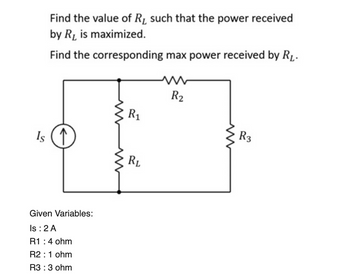
Transcribed Image Text:Find the value of R1 such that the power received
by R1 is maximized.
Find the corresponding max power received by RL.
w
Is ↑
Given Variables:
Is: 2 A
R1 : 4 ohm
R2: 1 ohm
R3 : 3 ohm
www
ww
R2
E
R1
RL
w
R3
Expert Solution
Check MarkThis question has been solved!
Explore an expertly crafted, step-by-step solution for a thorough understanding of key concepts.
bartleby
Step by stepSolved in 2 steps with 1 images
Knowledge Booster
Background pattern image
Similar questions
- Please help answer these questions. Need ASAP. Thank you!arrow_forwardWhat do the dials and buttons mean? How would you use this?arrow_forwardUnit 19 Elec Princ LO2 2022 2023.pdf - Work - Microsoft Edge https://moodle.nptcgroup.ac.uk/pluginfile.php/1421751/mod_resource/conte.. !!!! a) I=9.3 /0° A4 mim f = 350 Hz Find: 24 22 b) Z1 Vi HH 11.1 μF E E + V 5 of 7 i) The values of V1 and V2. ii) The value of the supply voltage and its phase angle. iii) Draw the circuit phasor diagram. (Z3) 31 Q2 V2 0.93 mH (For each section provide your answers in both polar and cartesian form.) Ơ X Qarrow_forward
- can someone show me step by step how to do this problemarrow_forwardin V1 R2 100k SINE(0 10 100) R1 100k D1 D V2 0 out D D2 V3 0 DC offset[V]: 0 Amplitude[V]: 10 Freq[Hz]: 100 T delay[s]: Theta[1/s]: Phi[deg]: Ncycles: anter 2019-2220 Figure 3-5 Clipper Circuit for LTSPICE Simulation C4. To specify the type of simulation, select "Simulate>>Edit Simulation Cmd" from the menu. Choose "Transient" and enter 30m for Stop time, 0 for Time to start saving data, and 1m for Maximum Timestep. Click OK. C5. Click Run to start the analysis. C6. Place two voltage probes (voltage probes appear when placed on a wire during simulation), one at the input side (at the top of V1) and another at the output side (at the top of D2) of the circuit. What difference do you observe between the input and the output waveforms?arrow_forwardO b. None of them C. Req=36.67 Q,P=-3.92W. O d. Req=61.5 Q,P=-2.34W. e. Req=36 0,P=-4W. estion 4 For this circuit, the values of 11, 12 and V are: yet swered 11 12 arked out of R1 R2 R3 R4 Is 15 A V 50 10 Q 10 Q Flag uestion Select one: O a. 11= 10J12 = 5 A, V=50 V O b. 11 = 5 A, 12 = 2.5 A, V=25 V O c. 11 = 5 A, 12 = 2.5, V=50 V O d. 11 = 2.5 A, 12 = 5 A, V=25 V Question 5 Find Rab- Not yet arswered 20 Q AAAA Marked our of TOSHIBAarrow_forward
arrow_back_ios
SEE MORE QUESTIONS
arrow_forward_ios
Recommended textbooks for you
- Text book imagePower System Analysis and Design (MindTap Course ...Electrical EngineeringISBN:9781305632134Author:J. Duncan Glover, Thomas Overbye, Mulukutla S. SarmaPublisher:Cengage Learning
Text book image
Power System Analysis and Design (MindTap Course ...
Electrical Engineering
ISBN:9781305632134
Author:J. Duncan Glover, Thomas Overbye, Mulukutla S. Sarma
Publisher:Cengage Learning