Introductory Circuit Analysis (13th Edition)
Introductory Circuit Analysis (13th Edition)
13th Edition
ISBN: 9780133923605
Author: Robert L. Boylestad
Publisher: PEARSON
expand_more
expand_more
format_list_bulleted
Bartleby Related Questions Icon
Related questions
Question
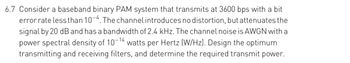
Transcribed Image Text:6.7 Consider a baseband binary PAM system that transmits at 3600 bps with a bit
error rate less than 10-4. The channel introduces no distortion, but attenuates the
signal by 20 dB and has a bandwidth of 2.4 kHz. The channel noise is AWGN with a
power spectral density of 10-14 watts per Hertz (W/Hz). Design the optimum
transmitting and receiving filters, and determine the required transmit power.
Expert Solution
Check MarkThis question has been solved!
Explore an expertly crafted, step-by-step solution for a thorough understanding of key concepts.
bartleby
Step by stepSolved in 2 steps with 2 images
Knowledge Booster
Background pattern image
Similar questions
- Q 6:- a) A certain sinusoidal at a frequency fmHz is used as a modulating signal in both AM and an FM system. When modulated, the peak frequency deviation system is set three times the bandwidth of AM system. The magnitude of those sidebands space at Ffm Hz from carrier in both system are equal. Determine the modulation index and bandwidth of FM and AM system. Find ratio power between power of two side in AM to power in the third side in FMarrow_forwardModify this circuit to extend the upper frequency limit to greater than 15 MHz. You may change the topology (i.e. configuration), but not the power supply voltage or collector bias current. The circuit voltage gain must be 46dB +/- 1 dB. Provide simulation results to show AC frequency responses of both circuits on the same plot, and annotate the 3dB upper frequency limit on both traces. Use typical ẞ values from the data sheet for the simulation. You may assume that 1% resistors are available in values below 100. The circuit must adhere to Standard Bias techniques. V4 Rser=0 SINE(0 0.02 10k) AC 1 VCC ୯ V2 +15V Cin1 1μ -VCC VCC R4 Rc1 147k 7k Q3 2N3904 R7 R6 9.09 20.5k Ce1 Re1 1.00k 10p Outarrow_forward(a) Explain on the AM Single Sideband Full Carrier (SSBFC) and compare to DoubleSide Band Full Carrier (DSBFC) on their:(iv) Carrier power.(v) Sideband powerarrow_forward
- 6.2. Consider a common telephone channel with the bandwidth limited from 300 Hz to 3400 Hz modeled by an ideal band pass filter (zero attenuation between 300 and 3400 Hz, complete rejection of signals outside the 300 - 3400 Hz range). You apply a square wave of 400 Hz, 1 Vpp amplitude, 50% duty cycle to the input. 6.2.1. How would the signal waveform look like at the output of this channel (time domain)? Draw an approximate sketch! 6.2.2. How would the spectrum of the signal at the output of this channel look like? Sketch!arrow_forward7-22arrow_forwardTopic : Amplitude Modulation 6.4)arrow_forward
- Question 2 (a) Briefly explain the advantage of the following Amplitude Modulation (AM) type and state ONE (1) application for each AM type: i. Double Sideband Full Carrier (DSBFC) ii. Double Sideband Suppressed Carrier (DSBSC) iii. Single Sideband (SSB). (b) The AM waveform for the modulated signal is illustrated in Figure 1. i. Calculate the percentage of modulation index, m. ii. State the type of the modulated signal. Justify the answer. iii. Write the equation for the modulated signal. iv. Calculate the percentage of power efficiency. 3V -1IV Figure 1arrow_forward78. To assure the same accuracy at both 100 Hz and 100 MHz, the signal level into a frequency counter must be A higher at 100 MHz B. higher at 100 Hz C. inductively coupled at 100 MHz and capacitively coupled at 100 Hz D. resistively coupled at 100 MHz and direct coupled at 100 Hzarrow_forwardA spectrum analyzer with an input impedance of 200 is used to measure the power spectrum of an AM signal at the output of a preamplifier circuit. The AM signal has been modulated with a sine wave. The effective carrier power, Pc, is 750mw, and each sideband, PusB and PLSB, is 120mW. Compute the following: 1- The total effective power Pr. 2- The peak carrier voltage, Vc- 3- The modulation index, m, and the percent modulation index. 4- The modulation voltage,Vm. 5- The lower -and upper - sideband voltages, VLSB and VUB. 6- Sketch the waveform that you would you see with an oscilloscope if it were placed in parallel with the spectrum analyzer.arrow_forward
- For an unmodulated carrier of 150 V and a modulated peak value of 230 V. What is the * percent modulation?arrow_forwardDraw the Full Duplex ASK diagram if the bandwidth is 18,000 Hz (500 to 18,500). Also find the carriers and bandwidth in both directions. Assume there is no gap between bands.arrow_forwardA 10 MHz TXCO is driving a receiver’s front end and has a frequency deviation of 4 ppm. It drives a direct down conversion RF front-end mixing the L2 frequency. What is the frequency offset at baseband due to the TXCO?arrow_forward
arrow_back_ios
SEE MORE QUESTIONS
arrow_forward_ios
Recommended textbooks for you
- Text book imageIntroductory Circuit Analysis (13th Edition)Electrical EngineeringISBN:9780133923605Author:Robert L. BoylestadPublisher:PEARSONText book imageDelmar's Standard Textbook Of ElectricityElectrical EngineeringISBN:9781337900348Author:Stephen L. HermanPublisher:Cengage LearningText book imageProgrammable Logic ControllersElectrical EngineeringISBN:9780073373843Author:Frank D. PetruzellaPublisher:McGraw-Hill Education
- Text book imageFundamentals of Electric CircuitsElectrical EngineeringISBN:9780078028229Author:Charles K Alexander, Matthew SadikuPublisher:McGraw-Hill EducationText book imageElectric Circuits. (11th Edition)Electrical EngineeringISBN:9780134746968Author:James W. Nilsson, Susan RiedelPublisher:PEARSONText book imageEngineering ElectromagneticsElectrical EngineeringISBN:9780078028151Author:Hayt, William H. (william Hart), Jr, BUCK, John A.Publisher:Mcgraw-hill Education,
Text book image
Introductory Circuit Analysis (13th Edition)
Electrical Engineering
ISBN:9780133923605
Author:Robert L. Boylestad
Publisher:PEARSON
Text book image
Delmar's Standard Textbook Of Electricity
Electrical Engineering
ISBN:9781337900348
Author:Stephen L. Herman
Publisher:Cengage Learning
Text book image
Programmable Logic Controllers
Electrical Engineering
ISBN:9780073373843
Author:Frank D. Petruzella
Publisher:McGraw-Hill Education
Text book image
Fundamentals of Electric Circuits
Electrical Engineering
ISBN:9780078028229
Author:Charles K Alexander, Matthew Sadiku
Publisher:McGraw-Hill Education
Text book image
Electric Circuits. (11th Edition)
Electrical Engineering
ISBN:9780134746968
Author:James W. Nilsson, Susan Riedel
Publisher:PEARSON
Text book image
Engineering Electromagnetics
Electrical Engineering
ISBN:9780078028151
Author:Hayt, William H. (william Hart), Jr, BUCK, John A.
Publisher:Mcgraw-hill Education,