There are lots of examples on the internet on how to build Arduino from scratch such as IN THIS LINK. I will like to do the same but with the esp32.
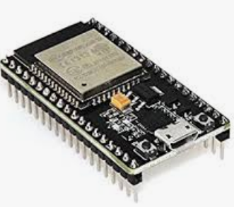
I have this development board:
And I am able to program it with the Arduino framework/IDE thanks to THIS VIDEO.
Now the question
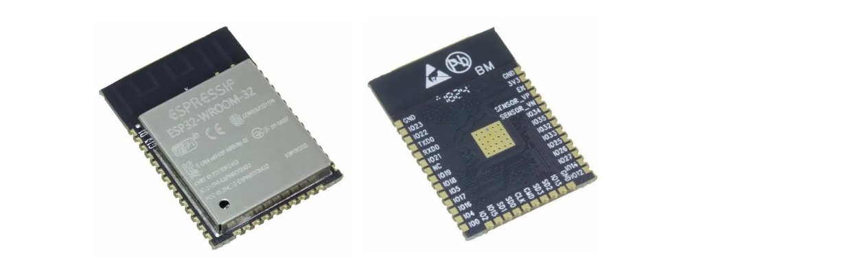
How can I flash my code and run it on a standalone ESP-WROOM-32 chip like this one:
I do not want to use voltage regulator etc as I am planning to run it from a 3.3V battery.
Before asking this question this was my research:
In this video (https://www.youtube.com/watch?v=n43rHugPbTg) Hugatry does exactly what I am looking for but he does not explain what pins he is using. Moreover what happens if I connect my 5v serial to the chip? will it burn?
I went directly to espressif website and looked for the schematics (https://www.espressif.com/sites/default/files/documentation/esp32-wroom-32d_esp32-wroom-32u_datasheet_en.pdf). It is hard to understand I just want to do something simple.
This blog (http://blogs.oregonstate.edu/copaps/resources/programming-esp32-on-custom-pcb/) explains how but the pins are different than my esp-wroom-32 chip.
Looking more on the internet/youtube everyone explains how to solder it. But I haven't found a diagram that will enable me to flash it and run my code. Also will I have to burn a bootloader like with arduino?
What I am about to try is to buy a 5V to 3.3V serial converter connecting TX with RX and RX with TX. Providing 3.3V power to the 3.3V pin and connect the last cable to ground. If I try that will it work?
-
It looks like you need to increase your general level of understanding of electronics. There is no "really simple" way except for buying a ready-made board. Look at the schematics of a standard ESP32 board to see what you need for support circuitry. As for your questions: 1) Yes, it will burn at 5V. 2) See my first comment. 3) See my first comment.StarCat– StarCat09/24/2020 07:49:02Commented Sep 24, 2020 at 7:49
-
The development board is basically the minimum circuit plus a USB to UART interface and a 3.3V regulator. Once you remove the regulator and its capacitors, and the USB interface and the few components for that, what you are left with is the bare minimum. You can't get much simpler than those development boards.Majenko– Majenko09/24/2020 10:08:01Commented Sep 24, 2020 at 10:08
-
The third link from the Oregon State University is unfortunately no longer available. It would be interesting to know what they wrote there.deralbert– deralbert09/14/2022 19:34:04Commented Sep 14, 2022 at 19:34
4 Answers 4
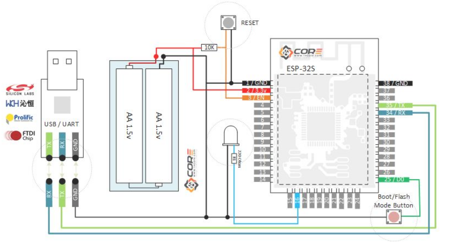
This is what I was looking for. The development board is not the minimum as @Majenko and @StarCat stated on their comments. This is exactly what I need as I plan to run my project from a battery. Moreover, the development board consumes a lot more energy when in sleep mode. I will even remove the LED that shows on this diagram:
So basically use a programming board like @KenVanHoelandt stated to program the board and then wire the esp32 like in the diagram above.
I got that diagram from this link:
https://www.14core.com/wiring-and-flashing-programming-esp-32-esp32s-with-usb-ttl-uart/
-
2you don't really need the buttons eitherdandavis– dandavis09/29/2020 05:56:01Commented Sep 29, 2020 at 5:56
-
Is this recognized as a programmer board by Arduino software (like the IDE or some plugin)?Balázs Börcsök– Balázs Börcsök04/17/2022 11:30:32Commented Apr 17, 2022 at 11:30
-
I am not sure what the exact minimum voltage esp32 requires, but make sure it is at least 3.6v that will be able to support it when wifi is being used . Also if you dont have a cut off circuitry for low voltage it might mess up your memory when the voltage is too low as the battery discharges.Anil Maharjan– Anil Maharjan02/28/2023 08:03:35Commented Feb 28, 2023 at 8:03
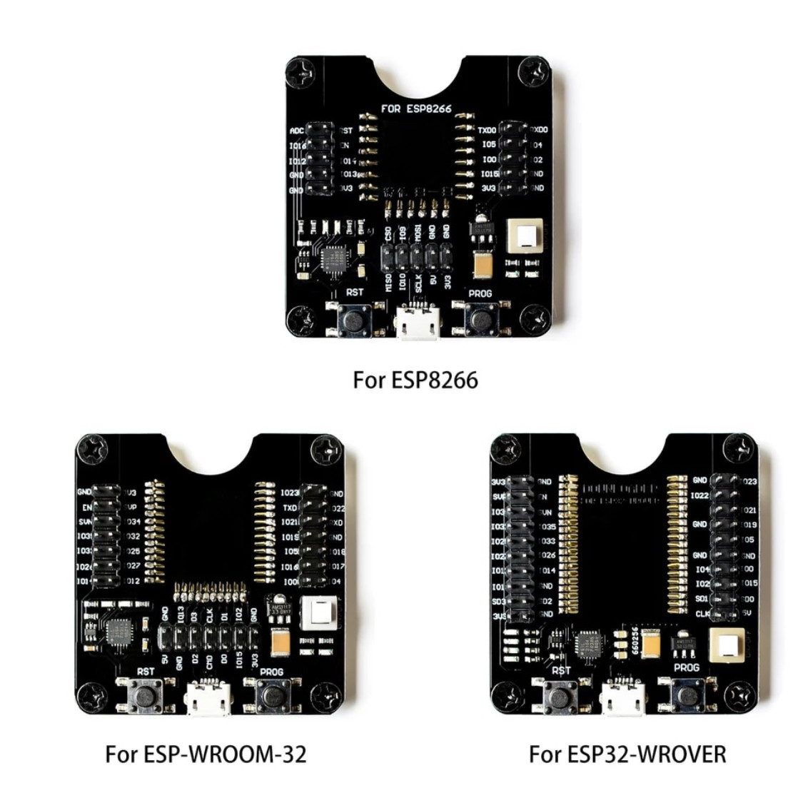
There are programming boards available to which you can plug one of these SOCs into them. There are different boards for different types of ESP SOCs. You can find them at popular Chinese vendors, and probably elsewhere too.
They look like this:
You could use wireless. First, use OTA programming (eg Elegant OTA) to burn a basic OTA uploader. Then, in principle, you can then upload any sketch you want so long as it ALWAYS has the basic OTA sketch included within your program.
-
1I don't think this answers the question. You still need support circuitry to auto-update, even if only updating over Wifi.StarCat– StarCat04/10/2021 16:23:40Commented Apr 10, 2021 at 16:23
OK, so the answer to the original question, how to upload code to a bare ESP32 that's not on a Development board, is as follows:
- Using an FTDI board, connect FTDI ground to ESP32 Ground, connect the FTDI TX pin to the ESP RX pin, then connect the FTDI RX pin to the ESP TX pin.
- Make sure you have a decent 3.3v power supply connected to the 3.3v and ground pins of the ESP32, do not use the FTDI power pins, the FTDI board doesn't supply enough power for the WiFi of the ESP32 and it will just keep rebooting.
- On the ESP32 connect the D0 pin to Ground to enable Flash mode.
- Upload your code.
- Disconnect D0 from ground and reboot the ESP32.
Job done.